Note:
Merry Christmas 2020, everyone! This is a mini how-to that will evolve during the holiday season. Have fun, come back, leave me a comment or tweet.
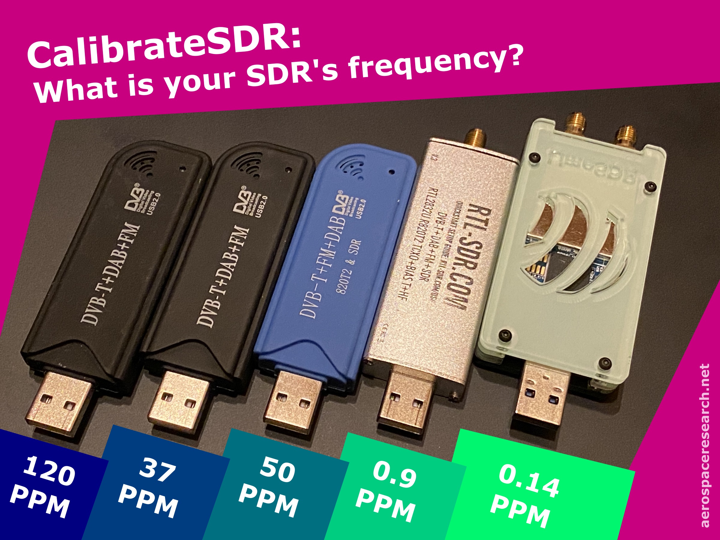
What is my SDR’s frequency?
For a current experiment I am doing with the NOAA satellites, I need precise knowledge of the received center frequency of their APT transmission mode (that one mode, that gives you weather maps for free, yeah!) at my SDR receiver. All of my SDRs oscillators drift and so does do their converters and thus the tuned frequency. Some more (RTL-SDR Black and Blue) and some less (RTLSDR Blog, LIMESDR MINI). This is usually stated as PPM (parts per million) as how precise the oscillator will clock the ADC that is sampling the antenna input.
To just give you examples of how much this can matter with 10 PPM:
NOAA satellite (~137,5 MHz): 10 / 1000000 * 137500000 Hz = 1.375 KHz
Your WIFI (~2 GHz): 10 / 1000000 * 2000000000 Hz = 20.000 KHz
So it can be way off-tuned for some purposes and calibration of your SDR receiver can be required.
What to use to calibrate?
There are quite a few ways to calibrate your SDR. Most of them resolve around measuring a signal on a frequency that you precisely know. So you compare the signal on the received frequency with the actually transmitted frequency and with his offset you can correct your SDR. That’s it.
For my NOAA experiment, I initially used Kalibrate-RTL by Steve Markgraf. That uses cellphone tower frequencies (GSM) to calibrate. That programme really works well. You can get it here (Linux: https://github.com/steve-m/kalibrate-rtl, Windows: http://rtlsdr.org/files/kalibrate-win-release.zip from web.Archive.org). The only two things I missed were these. I wanted to have this as a native Python code to use it with my other Python stuff. Okay, minor thing. And then unluckily, one of my ground stations is so remote in the beautiful Lower-Saxony region that there is hardly andy GSM coverage that Kalibrate-RTL simply did not work. So that is big hurdle.
So I needed to get another source for my calibration that all of our ground stations could use and I understand well enough.
The power of DAB+Step!
If you live in Europe (like me) or a few other places, you could find DAB+ that you could use (check the map on wikipedia). DAB+ is Digital Audio Broadcasting and will hopefully some day really really really replace classical UHF radio (before everything will be migrating to the internet…). DAB towers are quite powerful and transmit several 10 kilometers. The net of dab towers is dense enough here in Germany. So both is a good start to consider taking it. But the main point is that even though I don’t understand the transmission details at all (after spending long 10 minutes looking into the European Standard: Radio Broadcasting Systems; Digital Audio Broadcasting (DAB) to mobile, portable and fixed receivers [ETSI EN 300 401 V2.1.1 (2017-01)]), there is ONE aspect I understand on a basic level and that I am going to use for my very own calibration tool:
The synchronization channel symbols that comprise the null symbol and the phase reference symbol
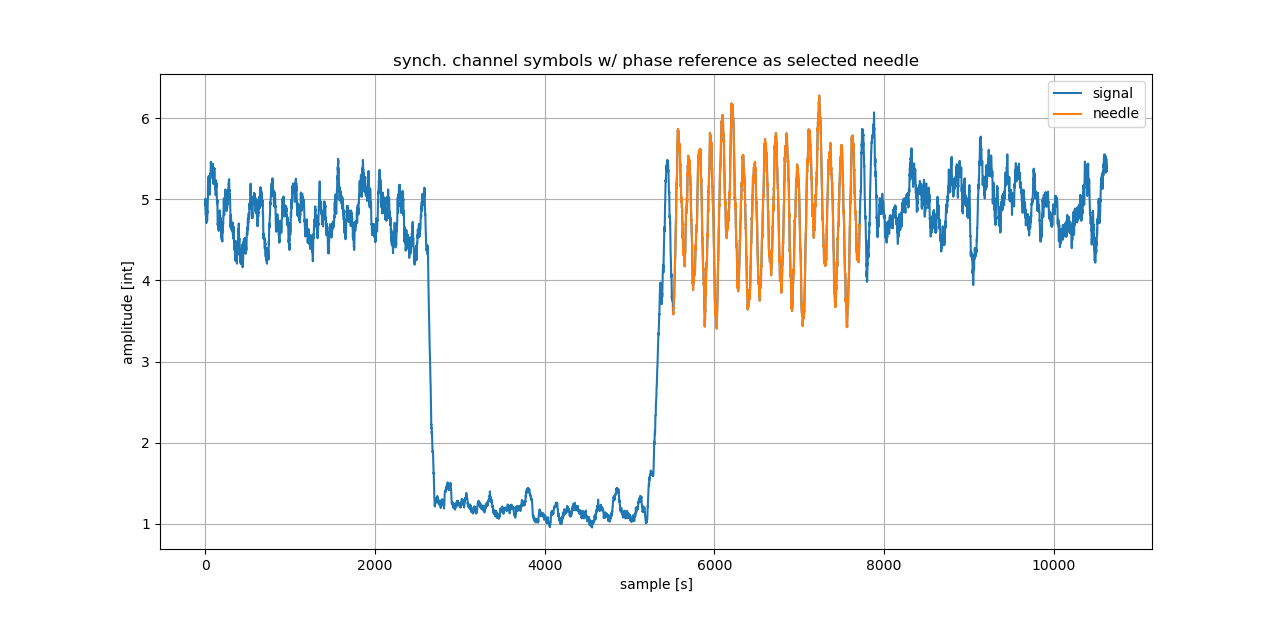
The null symbol and the phase reference symbol are at each data-blocks start. They are transmitted every 96ms and the samplerate is 2048000. The null symbol is as its name says a time-interval without any data transmission. ETSI also states its power should be maximum half the power of the transmitted data (paper: „Receiver Synchronization for Digital Audio Broadcasting system based on Phase Reference Symbol„, by Arun Agarwal, Member IEEE, and S. K. Patra, Senior Member, IEEE, DOI: 10.1109/ICEAS.2011.6147188).

So it is easy to find and it is used for fast but rough locating the data block start. For fine locating the data block start, the phase reference symbol must be used. Sources in the internet states that DAB-radios are knowing the reference patterns and are searching/correlating for it with the pattern. My code is just lazy and detects the end of one null symbol’s position and then takes the following samples (as amplitudes) as the needle. With this needle the following phase reference symbols are being found in the big haystack.
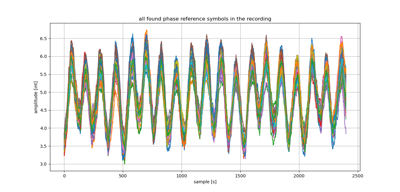
Of course this is only working under a few assumptions. The phase reference symbol should not change. The SDR oscillator should provide decent precision and stability so it does not change the incoming signal and/or needle. And lastly, the received SNR must be sufficient enought to detect the null symbols in the first place.
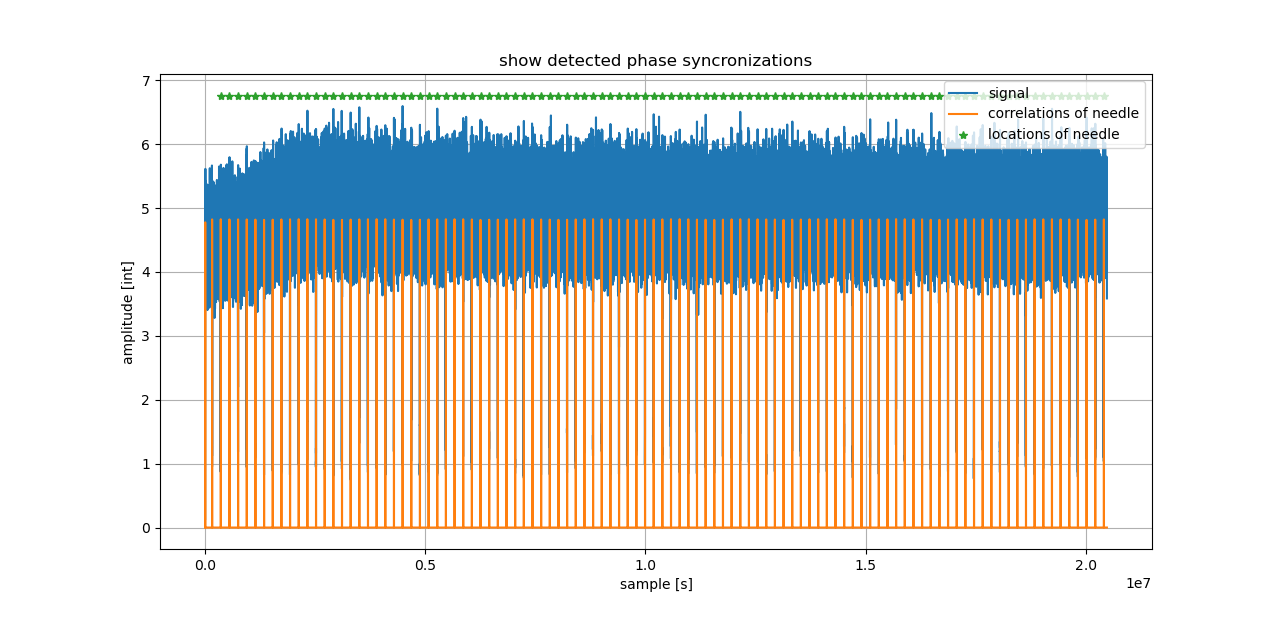
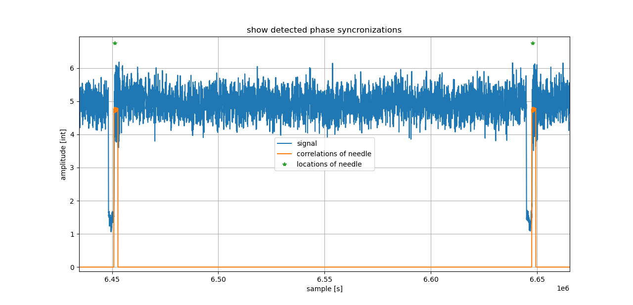
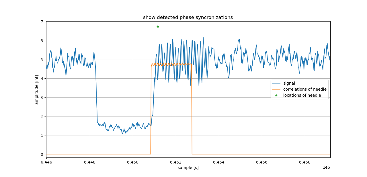
That is about all my CalibrateSDR tool is doing.
Calibrate your SDR with CalibrateSDR
For now, CalibrateSDR can only load in DAT or WAV files as 8bit-IQ files. So you either record it with rtl_sdr or you can use SDRsharp. More features will come.
I have tested it with several SDRs. RTLSDR dongles with R820T (Black) and R820T2 (Blue) chips and without temperature controlled oscillators (TCXO). The RTLSDR dongle from RTL-SDR.com (Blog) that has an TCXO. And the LimeSDR Mini (limesdr mini) from limemicro in the CrowdSupply kickstarter edition.
All were used with SDRSharp to record on DAB+ channels. For LimeSDR Mini I did not manage to get the python library to work. That will be investigated later, but for now the SDRsharp recordings are fine.
Commands:
CMD> python.exe cali.py -m dab -f YOURFILENAME -rs 2048000 -gr
If your recorded IQ file was sampled with 2000000 samples/sec, what we did with our LimeSDR Mini, then just change -rs 2000000. If you sampled with -rs 2048000 you can also omit it, because 2048000 Hz is also DAB+ default and set as default in CalibrateSDR.
With -gr you activate the graphs as shown before. The other options are planned to be included as soon as I have time or I understand them better :).
So here you go. If this was TL;DR, you can now skip the rest and try CalibrateSDR. The rest is only some results and what I still want to do. You can find my files here, download them, and then have fun test it with CalibrateSDR.
Results aka What is my frequency now?
So far, I tested 5 different SDRs and got various results. As expected the generic RTLSDRs are the most unprecise / temperature unstable ones. Best results I got with the RTLSDR V3 from rtl-sdr.com blog (blog) and with LimeSDR Mini from limemicro. The following graph is just a quick check with two consecutive measurements of 10 seconds each to check the stability. With 10 seconds you get about 104 phase references so that statistics can be done, and the repetition showed that at least during a period of about 30 seconds the temperture influence was low. Never the less a measurement to show the temperture influence will be interesting and is planed for later.
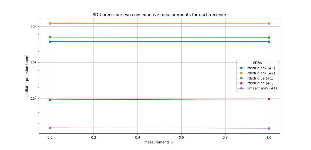
An interesting finding was to see that LimeSDR Mini is even more stable than even limemicro is stating. Our tests were always in the 0.1 PPM range. On their crowdsupply kickstarter page (see results in table below) it is stated for 1 PPM (with 4 PPM when stable). Me and the European Space Agency (ESA) backed it beack then for space projects, and at least it is me now with this NOAA satellite experiment that has the benefit of this ultra stable oscillator on board. And also the RTLSDR V3 is as expected with 0.9 PPMs and as stated in their datasheet.
| Oscillator Precision (limemicro) | Oscillator Precision (Kalibrate-RTL) | Oscillator Precision (CalibrateSDR) | ||
| RTLSDR black | generic | ? ppm | N/A @ GS | +/- 50 ppm |
| RTLSDR blue | generic | ? ppm | N/A @ GS | +/- 50 ppm |
| RTLSDR V3 blog | rtl-sdr.com | ? ppm | +/- 2 ppm | +/- 1 ppm |
| LimeSDR | limemicro | +/-1 ppm initial, +/-4 ppm stable | N/A | N/A |
| LimeSDR MINI | limemicro | +/-1 ppm initial, +/-4 ppm stable | N/A @ GS | +/- 0.1 ppm |
| HackRF One | Great Scott Gadgets | +/- 20 ppm | N/A | N/A |
| BladeRF | Nuand | +/- 1 ppm | N/A @ GS | TBC |
| add yours | … | … | … | … |
** BladeRF TBC, tested not yet done.
What is next?
Now I can return to my NOAA satellite experiment and use CalibrateSDR for it. I will link it here as soon as it will be finished. Stay tuned.
In the meantime, it would be cool if you could tell people here more about your SDR’s calibration results. A few famous SDRs like HackRF, BladeRF, PlutoSDR and others are still missing. I don’t have access to them so their PPM results could be sent in by you via email or in our zulip-chat. Such a small database could be handy.
And lastly, feel free to alter and modify the code. I will be more then happy to see pull requests for it. If you understand GSM, DVB-T and other signals, please add those features, too. Not everyone is living in Europe and their region maybe do not use the DAB+ radio standard. It would be great so see more people using this mini tool.
Get involved…
Use the tool: https://github.com/aerospaceresearch/CalibrateSDR
Discuss: in our ZulipChat
Expand: it with GSM, DVB-T, etc… it is under the MIT licence