[GSoC 2020 | MOLTO | Brandon] Refactorization MOLTO

Introduction

Hi, my name is Brandon Escamilla, I am an Aerospace Engineer by Universidad Marista de Guadalajara (Guadalajara, México). This is the second time I got selected for the GSoC. I am really grateful for this opportunity. This time, I came along with a proposal to improve the actual MOLTO project. The same I did work the last year. MOLTO is a big project, which has tons of work before going to production. Last year, I worked in a way to connect MOLTO with a user interface, it was not an easy work since MOLTO is a Matlab tool which requires special connections and is not as easy as consuming a normal API, so I did create an API with Python/Flask to communicate my requests from the Frontend to Matlab directly. It did work, we did communicate successfully with the Matlab tool. But there were some problems we need to resolve in order to have a „production environment“. At the end of the GSoC, we had a UI created in React.js, an API using Flask, and a local database using SQLite. This was enough to prove the architecture I wrote in my proposal, easy architecture to get to the web those projects created in Matlab which can’t go to production because Matlab closed license.

Last year blog: [GSoC 19′ |UC3M ] MOLTO – Mission Designer]

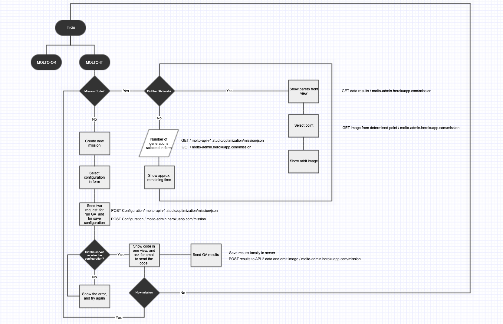
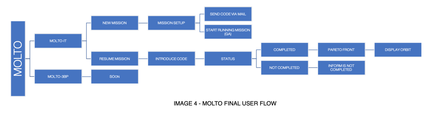
So, here you have the new flow of MOLTO from a route-based perspective, and from a logical flow.

The main issues that needed to be solved before to go to production were the ones I will list below:

  1. Error communication between Matlab and Python.
  2. Delete Real-time communication between UI – Python – Matlab. (Sockets)
  3. Create a new service based on Codes to retrieve the mission.

But there were also some improvements needed to be added with lower priority:

  1. Friendly user interface for new users.
  2. New Design
  3. Create a database in production to save missions configuration and results.
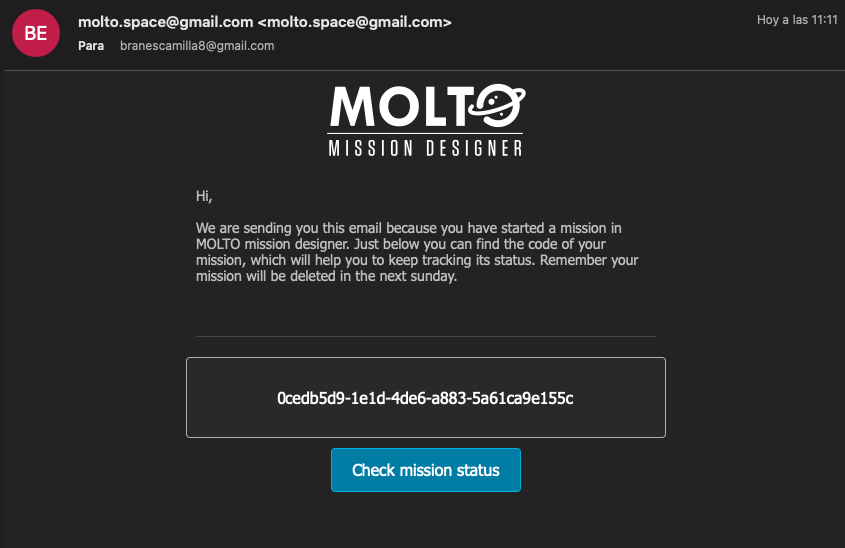
  4. Create an email service to send mission codes.
  5. Create CMS to add information in an easy way for maintainers.
  6. New view for the service based on codes.
  7. Improve deployment of Frontend.
  8. Response optimization from Matlab Genetic Algorithm.
  9. Toy problem for new users.
  10. Optimize responsive views of the site.
  11. Improve Celery implementation for Background tasks.

Before continuing, I would like to add that after GSoC, I continued working on MOLTO, adding small features, and improving user experience as fas as I could. In our constant communication between my last mentor David and I, he did invite me to start a research stay in the University Carlos III where he was doing his Doctorate. This led to another experience where David has been my bachelor’s degree thesis advisor. (A good story thanks to GSoC! ?)

Hands-On!

Once accepted, I started working on my proposal which did look something like this:

1. CMS Implementation

For this purpose, I did use an open-source application called Strapi, which allows you to develop a CMS locally and in production in an easy way. It helps you to develop the database, API, endpoints, CDN requests, models, emails, and more…

I did install Strapi locally and started creating the services were needed for MOLTO which can be divided in this way:
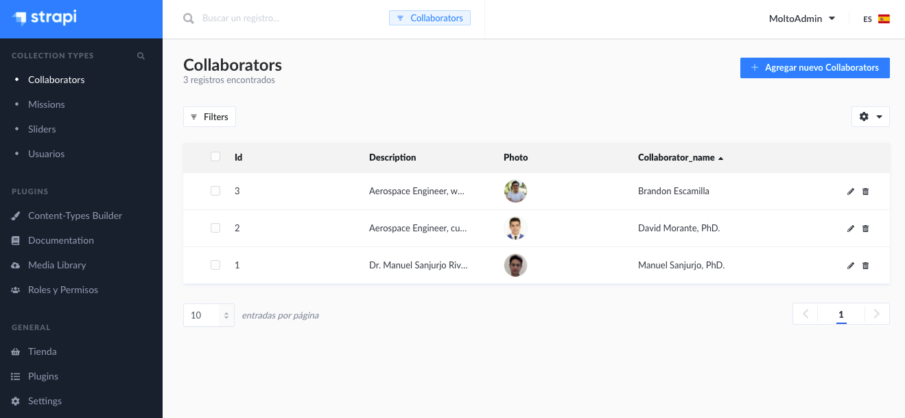
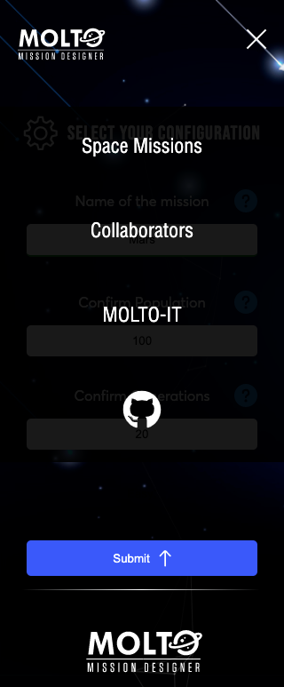
  1. Collaborators
  2. Missions
  3. Users
  4. Email Service
  5. Motors

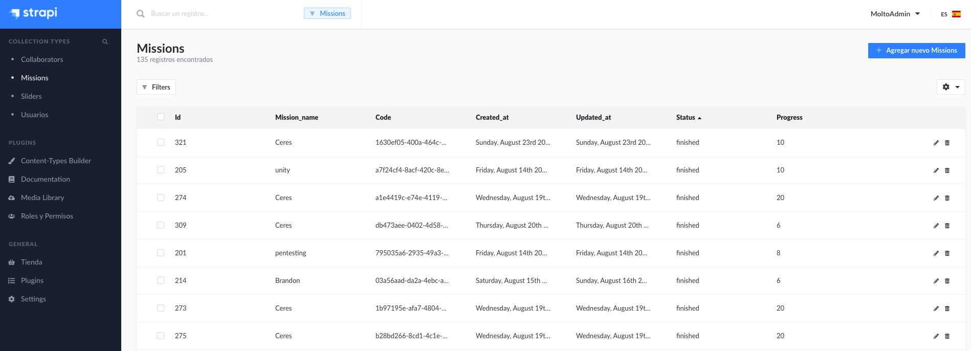
Once I create all the services described before, I just started to launch the CMS to production. The easiest way to do this is using Heroku, which allows you to have an app in production with very few steps and configuration. Finally, you can find the Admin in this URL: https://molto-admin.herokuapp.com/admin, Of course, it has a login and just the maintainers of MOLTO can access. But I leave you a few screenshots, so you can see the interface.

I am using a PostgreSQL database which actually is a plugin from Heroku app. ✅

And this is the documentation of the endpoints:

https://molto-admin.herokuapp.com/documentation/v1.0.0
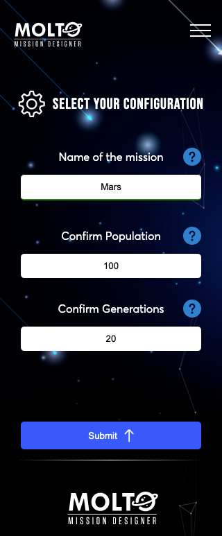
2. New design MOLTO

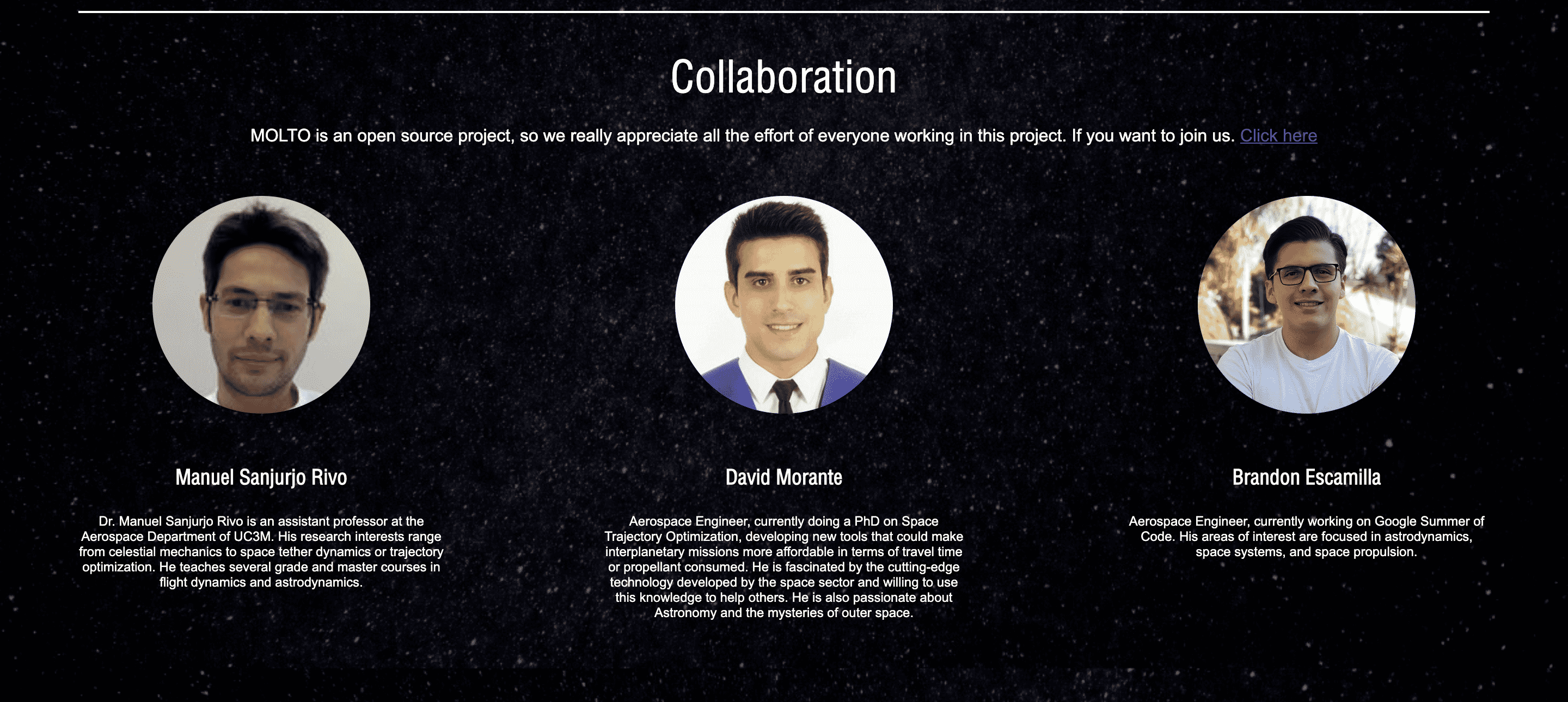
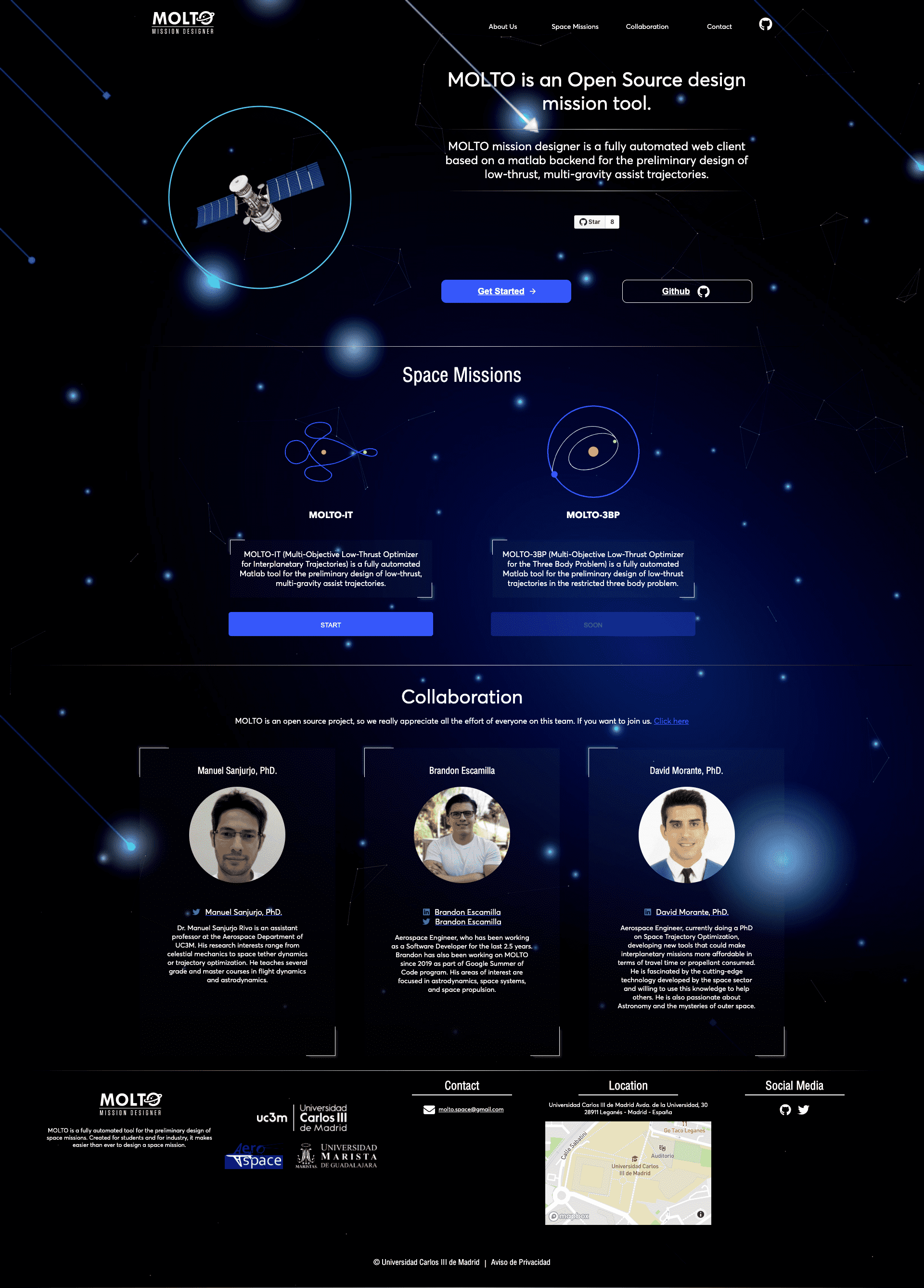
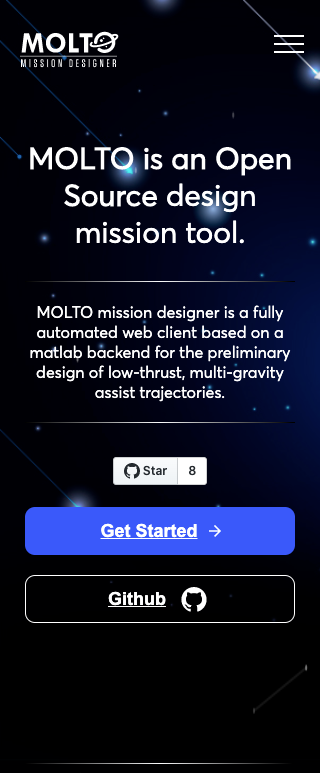
Before going to production we needed a new design because the first one was more like an MVP, finally, I added a link to the old site, the designs, and the newly implemented design. Almost all the components of the website did change, from the home to MOLTO-IT, and also new views were added.

Here I will leave you some screenshots of the old design and the new design. (I will include the links in case you want to check it out )

New site: https://molto-it-ui-old.vercel.app/

New site: https://molto-it-ui.vercel.app/

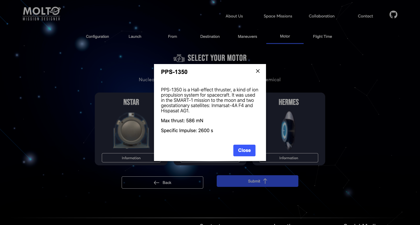
Another new feature is in the motors section of MOLTO-IT, where you can actually see the motor configuration clicking in more information.

Another feature is the mobile version of MOLTO and the new menu, at this moment is really important to have a good mobile version of websites, since most users will visit your site from their cellphones. So, I did refactor the mobile version and right now is good to work from cellphones.
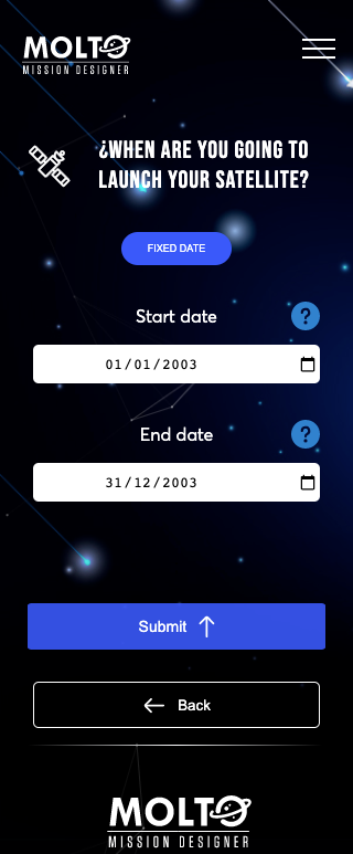
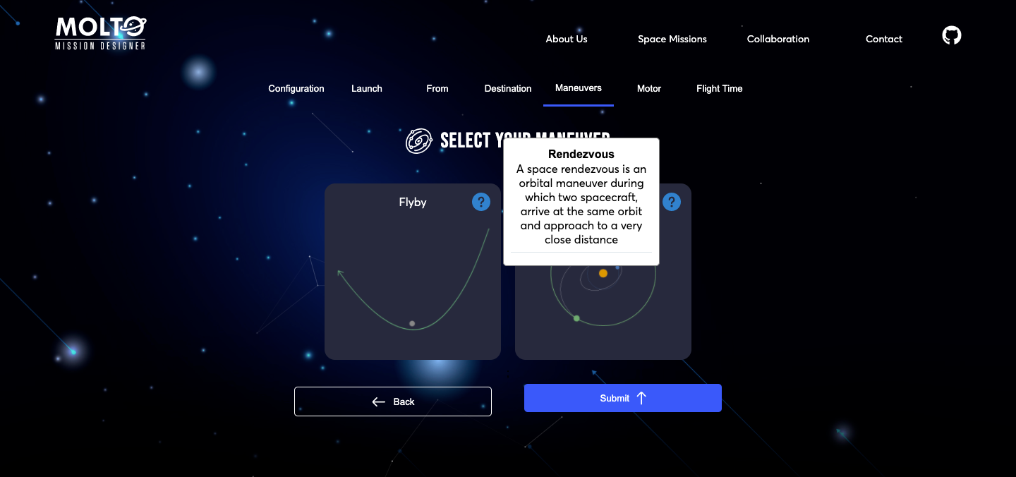
3. Tour MOLTO

In order to have a better experience in MOLTO, I did try a lot of ways to do it. I started using a library called React tour, and after another one called React joyride, but I did notice that those were very intrusive with the user experience and that actually the performance of the application was really bad when using both libraries. So I did prefer to create my own component which shows an information icon and if you hover on desktop or click it in mobile, display a box with useful information in order to know what to add in the inputs or what are the inputs for.

I found this way less intrusive and useful in my opinion. Here you have one screenshot of this component.

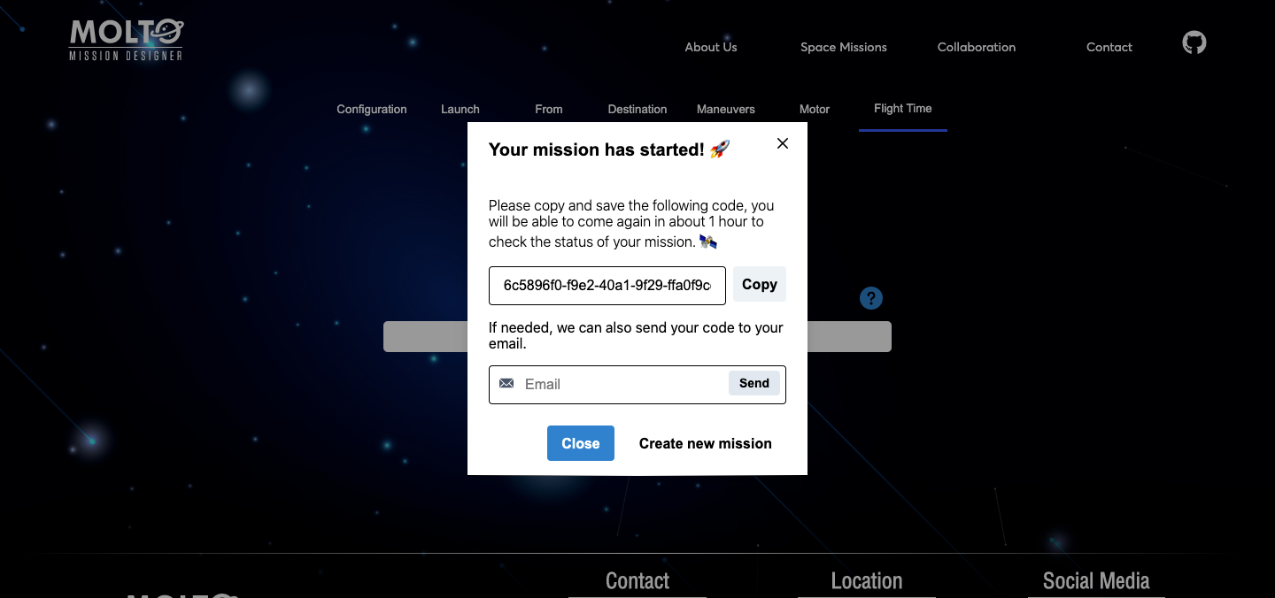
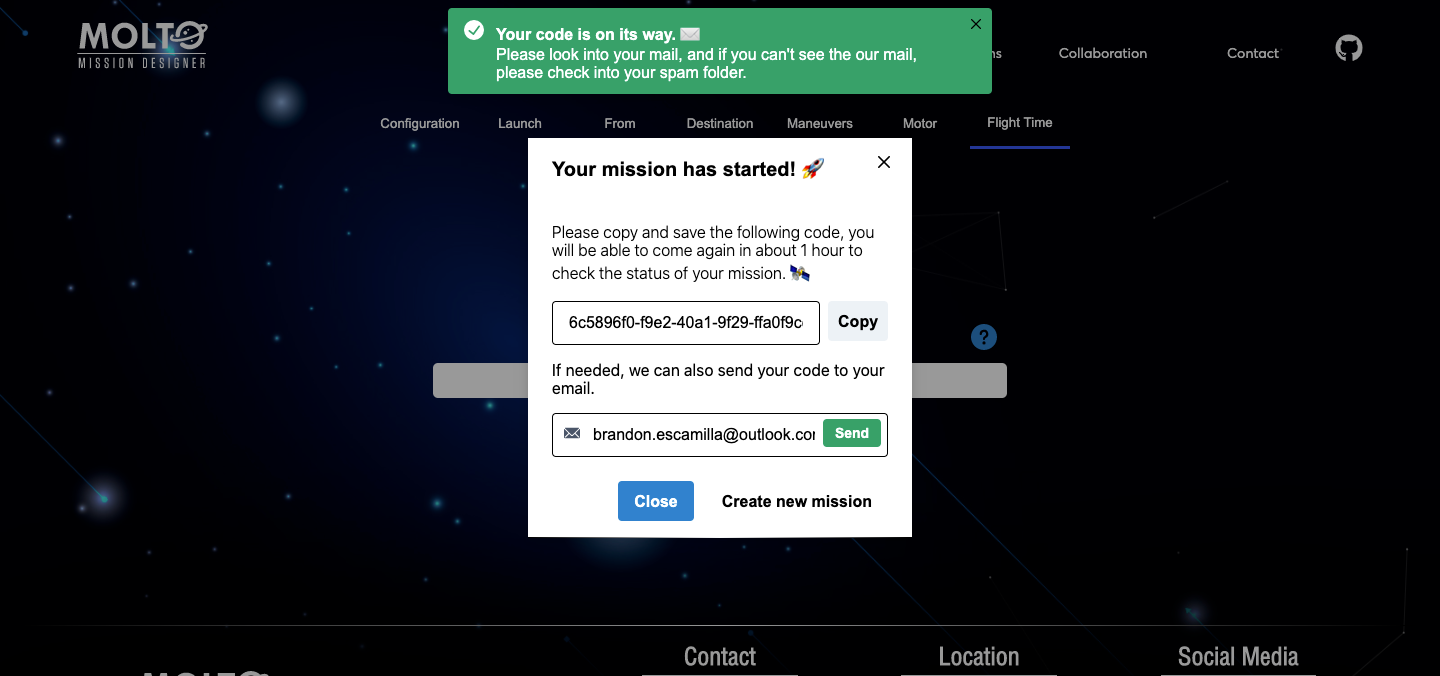
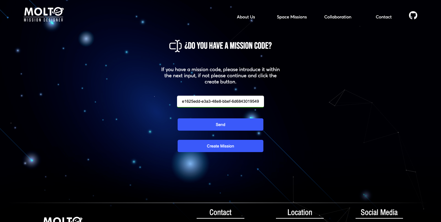
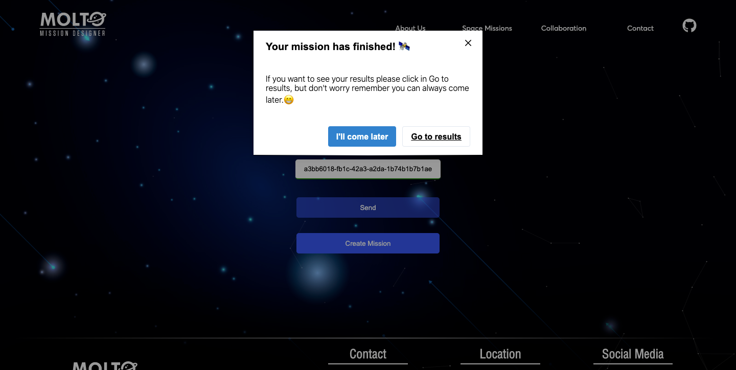
4. New service for creating a mission or search for a mission created.

One of the requirements of the last year was to create a UI with the possibility to see how the genetic algorithm evolves in the time. This was possible, but also a bad idea from a user perspective. Once they select their configuration, they needed to be waiting for the response of the API, this time could go from 3 minutes to 10 minutes – more generations, more population, more time-, which is the time Matlab started the genetic algorithm, in this point Flask opened a socket to start consuming the files were being created in real-time in a directory of the server where MOLTO lives. This was working well but just in one situation: A mission with really low generations and population, since this kind of missions will return results fast. So, once you started a mission with more than 30 generations and more than 50 population, you needed to wait a lot of time before the sockets could return the first generation, and this leads to another problem if the user wanted to see the final generation, the user needed to wait from minutes to hours, without closing the browsers – once you closed the browser, the socket connection finished-. So in the meantime between GSoC and GSoC, I created a new architecture based on codes where you create your mission and the website returns you a code, and also the possibility to send the code to your email, so you could return, in 1 hour, 1 day or 1 week, and all your results will be there stored in the database. Of course, this was a lot of work, I need to almost change most of the logical code was created to connect with Python via sockets. And also new views needed to be created to retrieve the mission, send the code to email, etc.

Almost in the middle of the second evaluation I start working on this, and after days of coding, the new service was available, here I will add few screenshots, but of course, you could to the MOLTO website.

The view which looks for missions, has an input where you need to put the code MOLTO gives you when you finished the configuration of your mission, this input has the ability to detect invalid codes, and also returns the current status of the mission. This is thanks to Celery, which is a tool that before was just running tasks in the background, but with the proper configuration, you can check the status of the mission in real-time. ?

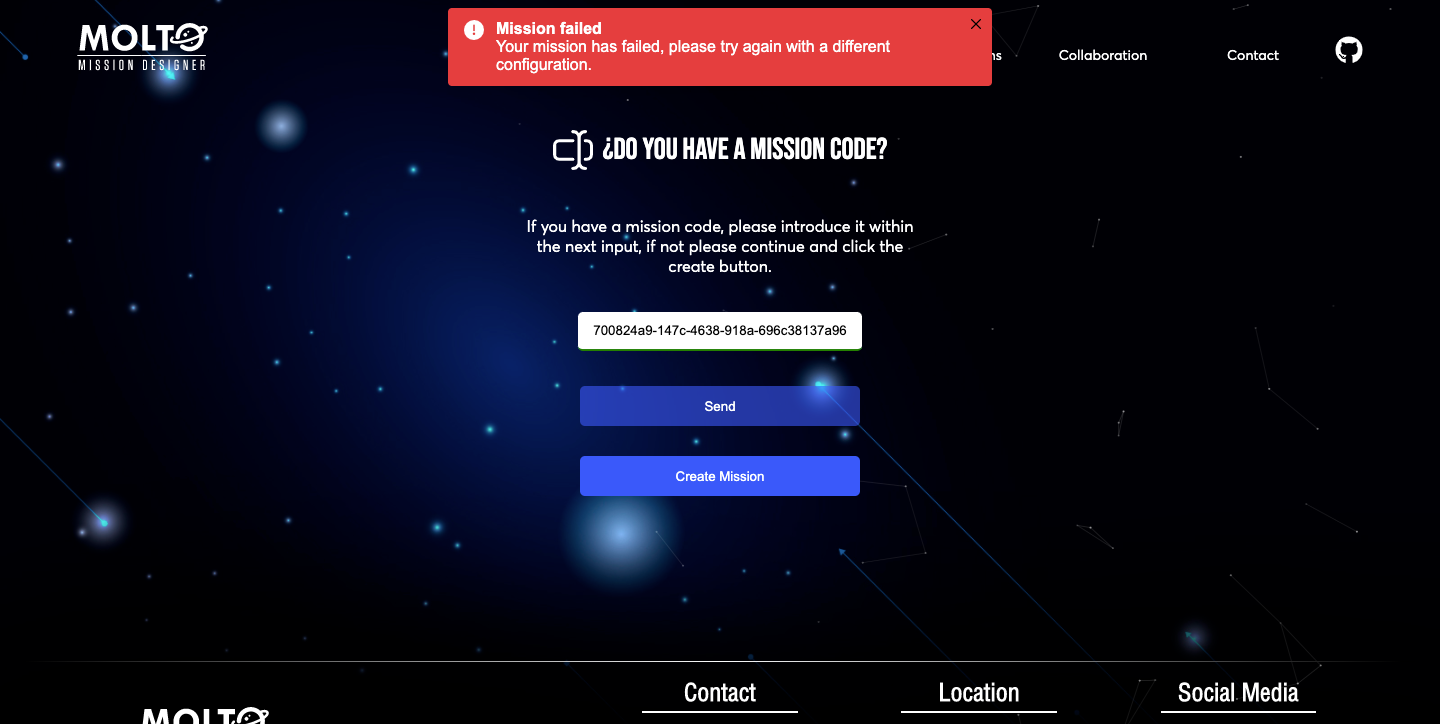
4. Celery and Matlab Errors

As I said at the top of this post, one big problem was that I had issues trying to connect Matlab errors with python, due to this once a mission failed, I didn’t know the real reason why it was failing. At the start, it was not a problem, because I was using always the same JSON for creating missions and testing. But once you put different configurations, it was randomly working, sometimes it works, sometimes it just crashes, and I didn’t know what was happening. So, this year, I decided to solve this issue, as said before, using Celery properly, and also the Matlab Engine For Python.

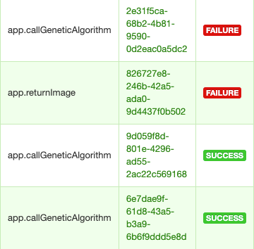
The big issue was that I was not adding some configurations to check the tasks in the UI of Celery called flower, and I was also not using some configuration to read logs from Matlab in python, It was a hard task, but finally, it is working, so I will put here one screenshot of the logs I am receiving in the server where I can know exactly why Matlab is not working.

I can also see all the missions in real-time in a dashboard, all the missions that failed, all the successful missions, and also the tasks that are running.

5. New host for Frontend

There are a lot of ways to host your frontend applications, we can host our frontend in the MOLTO server, or maybe in another service like AWS, etc. But I recently started using Vercel to host other projects, and it was a great experience since you can have multiple environments for testing, production, development, etc. All of this in one place, connected to your repository in Github or to your CLI. It makes easier the development and that’s why it is the platform MOLTO will be using for frontend hosting.

We have right now two environments dev, and production, all the changes that will be applied to the UI of MOLTO will pass first by dev, after approval all these changes could be applied to production.
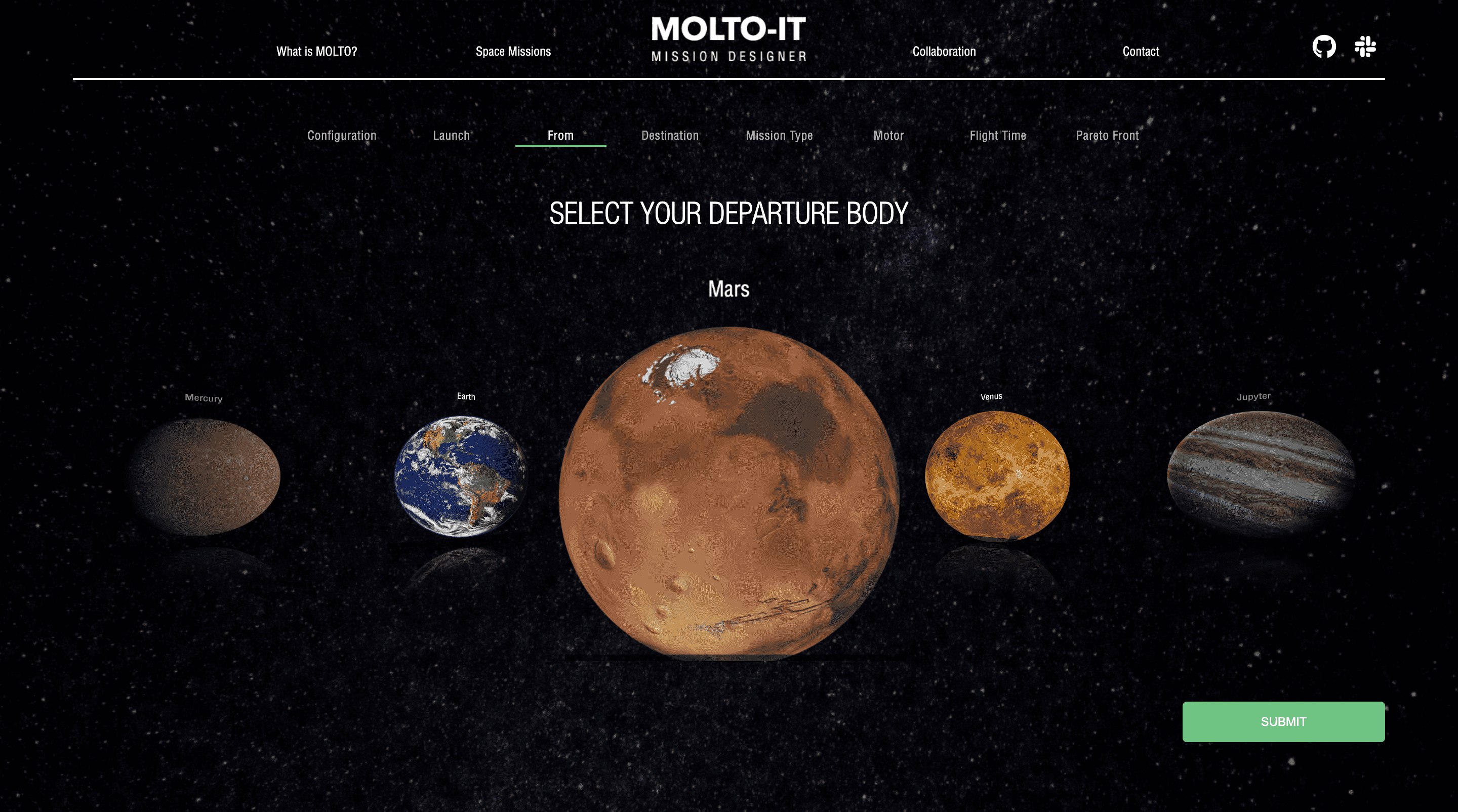
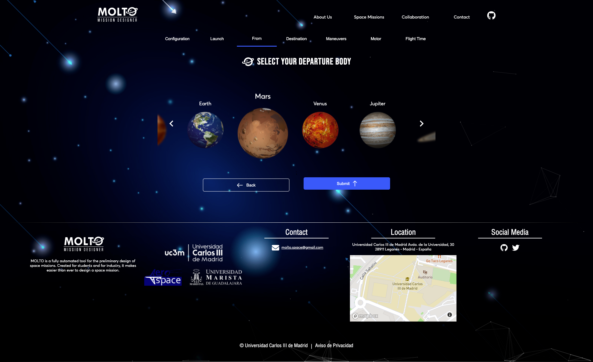
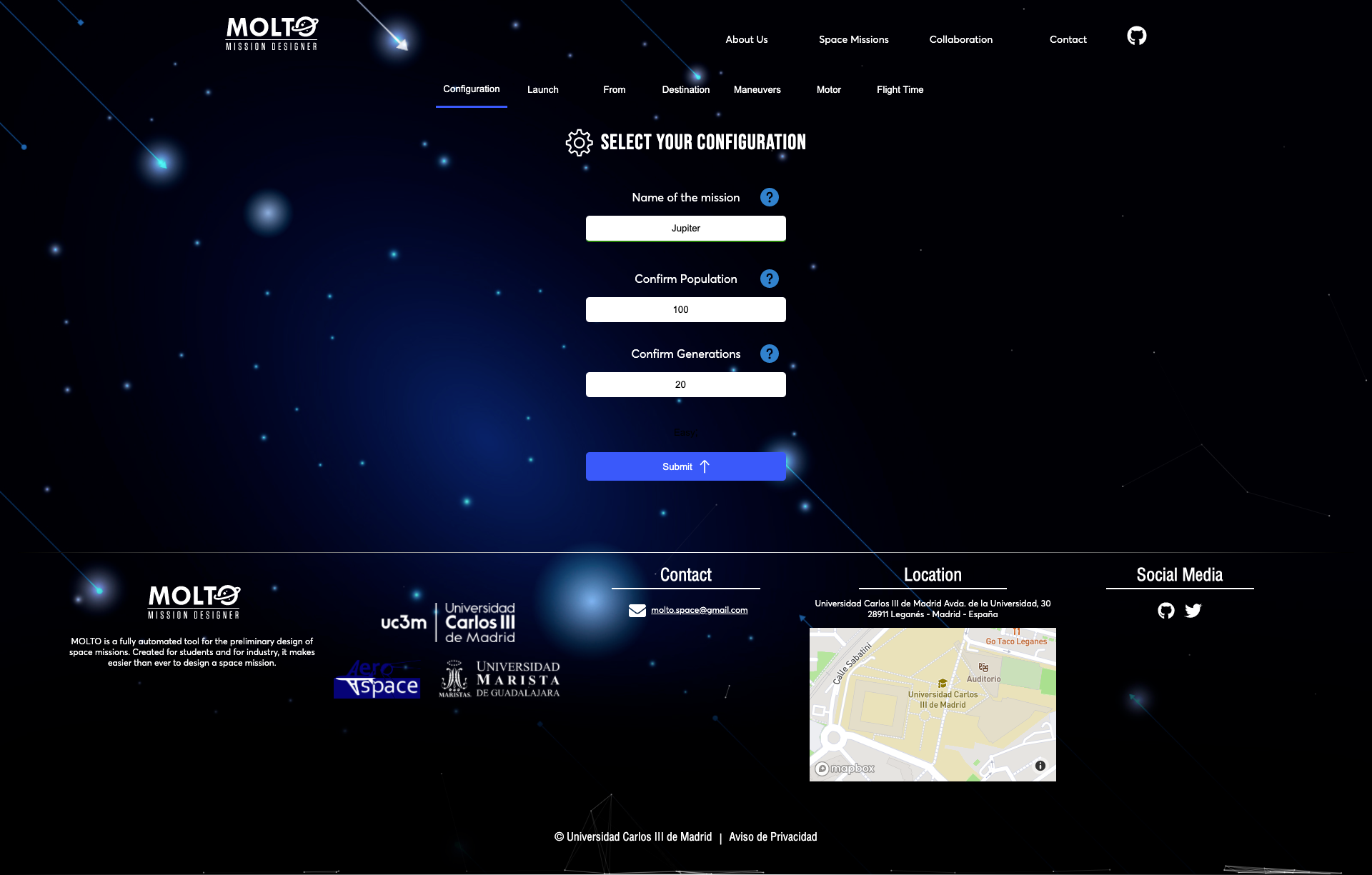
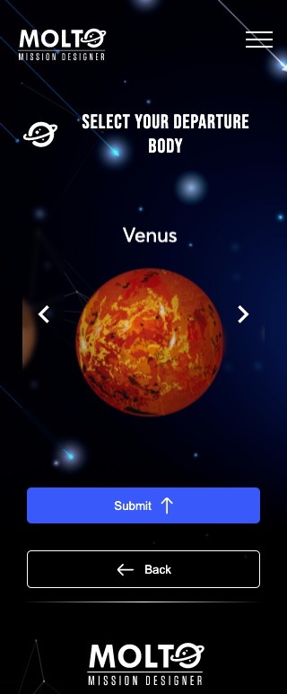
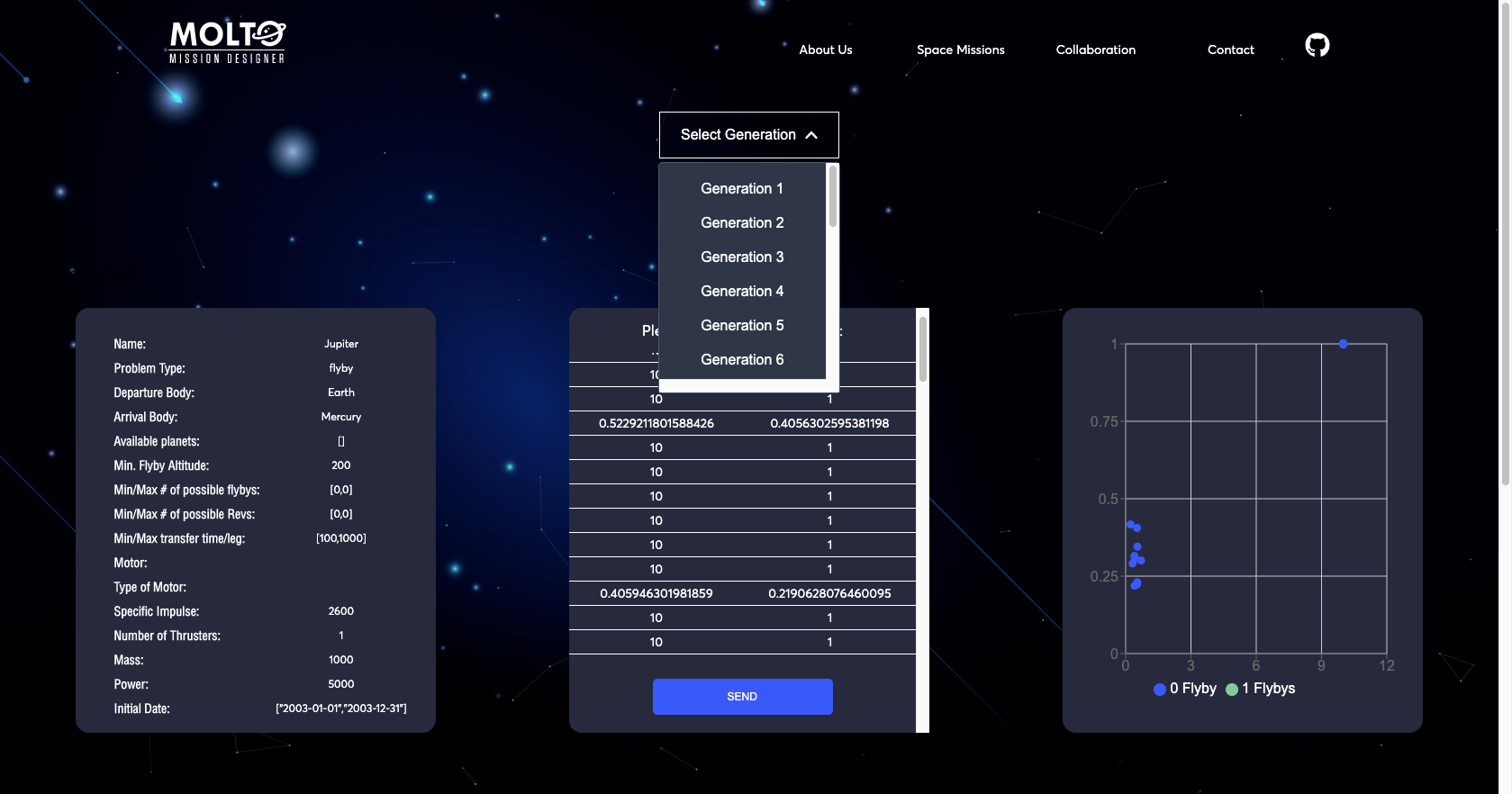
6. Toy problem

One problem I faced when I was demonstrating MOLTO was that I was the only person who knows how to use it. That was a problem because you can’t deploy an application to production if it is not intuitive.

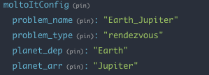
In order to improve this situation, I used the based architecture of data management called Redux to pre-load a problem, so every time you enter to MOLTO-IT you can change just the name and go to the last tab, click send, and here you have a useful mission, from Earth to Jupyter. So you can test this mission, and actually see the Pareto front without any problem.

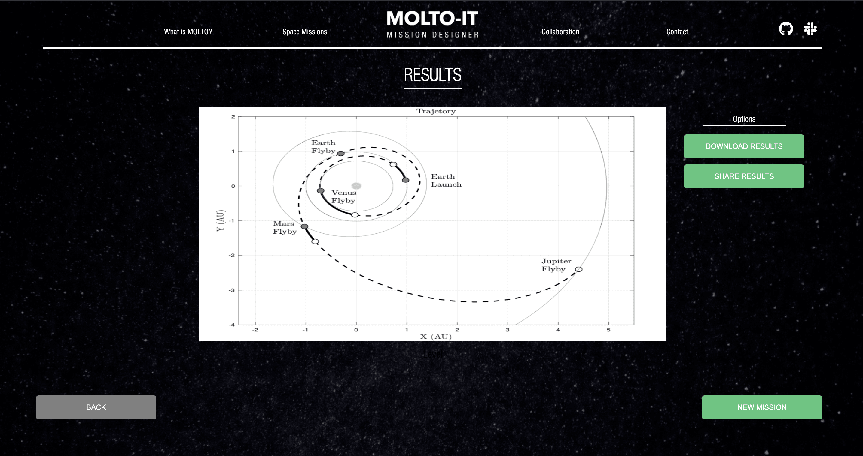
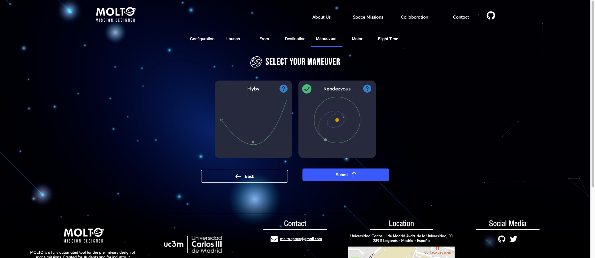
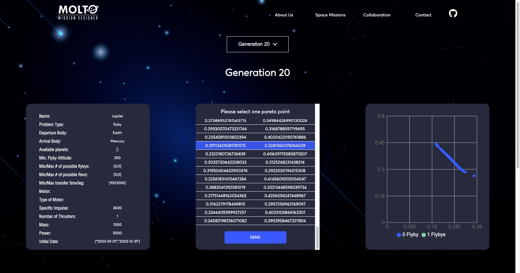
7. New flow with code – Pareto Front

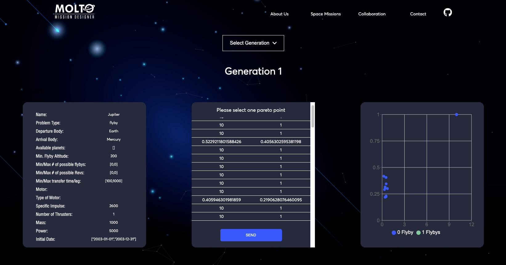
I’ve been talking about the new flow but I didn’t show you how it looks after you put a code that has a finished state. Well, actually, this view has some improvements also.

The first one is that you are able to see all the results from generation 1 to the last generation with its respective results. So you can test any value to plot the orbit. You can also see in real-time how the chart changes once you select another Pareto point.

Conclusion

It was an honor to work again in the Google Summer of Code 2020, finally, I would say I finished what I proposed at the start of this project. I also want to thank all the persons who make this possible, Dr. Manuel Sanjurjo, Dr. David Morante for guiding me, and helping me every time I have issues or problems to resolve. I also want to thank you for the research stay at UC3M, I hope I can continue working along with both in this and other projects.

I also want to thank Andreas Hornig for being there for any question and always provide the necessary stuff to keep working. Also for always remember me the deadlines ?, and pushing me to give the best of me.

As far as I know, this is the last GSoC in which I can contribute as a student ☹️, but my next goal is to keep contributing to open-source and why not contribute also as a mentor if possible in the next GSoC’s. I would really like to share all that I’ve learned during these 2 years. ?

Thank you for reading.

Brandon Escamilla

Useful resources:

  1. Production website: molto-it-ui.vercel.app
  2. Repository: https://github.com/uc3m-aerospace/MOLTO-IT
  3. Email: brandon.escamilla@outlook.com | brandon.escamilla@aerospaceresearch.net

[GSoC2020|OrbitDeterminator|Nikhil] Tracking Continuous and Sporadic Signal of Satellites – Wrapping Up

Introduction

With increasing popularity in CubeSat technologies, it has gotten ever so important to have low-cost systems that complement the economical and self-reliant nature of today’s cubesats providers. One of the most important parts of an end to end small satellite business is ground-based tracking. Satellite tracking provides valuable information on the whereabouts. Satellite tracking industry is booming with the use of large antennas and high power transmitters at cost-prohibitive nature but at the cost of expense and lead time. 

It is thus important to use an alternative tracking method, for example, Doppler Tracking. Doppler based orbit determination uses a doppler frequency shift to convert to a distance problem. To do doppler tracking, one has to first track the frequency of the signal. This way the cost of the tracking system is kept low because equipment needs beyond the essential receiver are small, at a minimum consisting of an amplifier and a variable oscillator. This project aims to provide a universal tracking solution for burst and continuous type signals of satellites.

Overview

This project aims to have a universal tracker for sporadic and continuous type signals. This requires the above workflow. Overall there are three main stages of processing before we arrive at our final track. Every stage has its own function and uses a particular algorithm. 

  • Stage 1: Pre-Processing
  • Stage 2: Decision Making
  • Stage 3: Tracking

Waterfall

Before the pre-processing stage, it’s important that we have our signal in the frequency domain, by taking the Fourier Transform. So, the program performs the FFT in chunks to improve memory performance and runtime. It then selects the desired channels of a specific bandwidth, as per the user’s requirement.

Signal Detection

FFT Averaging

Before we make a decision, whether a certain FFT frame has the signal or not, we need to remove some consistent artefacts present throughout the duration of the recording. 

The basic idea of averaging for spectral noise reduction is the same as arithmetic averaging to find a mean value. This operation is a type of low-pass filtering that can reduce high-frequency noise.

APRS signal example

Calculating an average spectrum involves averaging across common frequencies in multiple spectra. So we subtract an average spectral frame from the sample frame in question. This improves measurement accuracy and also helps to compensate for a low signal-to-noise ratio.

Decision

The decision of whether a signal exists in a given FFT frame is done by checking the neighbouring frequency bins of a sample bin (n) that all have bin magnitudes greater than that of a dynamic threshold.

an illustration of the decision making

This threshold is calculated as follows:
Threshold = Mean + SD + safety gap

Black indicates selected bins
A NOAA signal’s full spectra; green(channel selected)

Tracking

Finding the center

Once the signal is found in a particular FFT frame, it is a matter of finding the centre of the geometric signal. To cover most signal types a generic approach has to be taken. This is why a spectral centroid is a good enough representation of the signal center.  A spectral centroid analogous to geometric center and refers to the balance point of the signal.

x(n) represents the weighted frequency value, or magnitude, of bin number n, and f(n) represents the center frequency of that bin.

Track Smoothing

The frequency track of the signal through the recording is curve fitted with a polynomial function of order 3. It is also important to remove outliers before fitting the data.

Waterfall (white-raw track, black-filtered track)
NOAA Waterfall Signal Track (white-raw track, black-filtered track)
APRS Waterfall Signal Track – (white- raw track, black – fitted track)
APRS Waterfall Signal Track (BW-10kHz) – (white- raw track, black – fitted track)

Outputs

The program can output spectral frame and waterfall plots of multi-channels and bandwidths specified by the user. The frequency track of the signal from the specified channels, when found, is finally stored in a JSON file. 

SignalChannel FrequencyBWWaterfallData
NOAA 137.62 Mhz32 kHzwaterfalljson
APRS-1145.825 Mhz10 kHz waterfall json
APRS-2 145.825 Mhz 10 kHz waterfalljson

Acknowledgement 

In the end, I would like to thank AerospaceResearch for giving me the incredible opportunity to work with them in Google Summer of Code 2020. I have learned a great deal and this journey has solidified my belief in open source for space. I would also like to thank Andreas Hornig for being the mentor of this project and extending his guidance and support, whenever needed.

Links


[GSoC 2020 | MOLTO-3BP | Ginés] Finite Fourier series approximation

1. Introduction

I am Ginés Salar, Aerospace Engineer by University Carlos III (Madrid, Spain). As this years‘ GSoC edition comes to an end, allow me an opportunity to give a comprehensive explanation of my contributions to aerospaceresearch.net. From my university’s department of aerospace research, there is an interest to develop and test preliminary trajectory optimizers. This has led, in recent years, to the development of MOLTO (Multi-Objective Low-Thrust Optimizer). Such a tool would provide a two-step optimization process for one in three scenarios conceived: IT (Inteplanetary Transfers), OR (Orbit Raising) and 3BP (Three Body Problem). In this post I will not go into the details of these engines but I strongly advice the interested reader to access [GSoC 19′ |UC3M ] MOLTO – Mission Designer.

My efforts try to improve upon the MOLTO-3BP, specifically the first step. The classical approach to this problem searches for a set of ballistic trajectories patched by instantaneous impulses. It is assumed that by reducing the fuel consumption of these impulses, the initial guess improves. After that, the engine moves to the second step and introduces the actual control optimization to adapt the orbit to a truly low-thrust mission. There is little knowledge about whether this procedure delivers the best result or merely a local minimum. Providing an answer to this question is what motivated the work done.

2. Work Breakdown

Parallel works by other students have attempted to provide a database with sampled non-keplerian periodic orbits. Initially, these efforts were aimed to replicate real missions, or to try to improve them using their objectives as a guide. The purpose of this database would be to propagate invariant manifolds from the orbits in order to find ballistic transfers that involve libration point orbits. Finally, the aforementioned patching process is carried out by selecting a suitable Poincaré section and analyzing the trajectories‘ intersections with this surface.

Under this environment, my main objectives were:

  • Generalize the capabilities of these functions.
  • Structure the code into a single body.
  • Translate the existing code to Python.
  • Emulate libration point orbits transfers.
  • Provide a new metric for the trajectories‘ suitability with a shape-based approach.

The first point, was to isolate all constants from the rest of the code and allow an easy access and control of the studied system. Furthermore, the most interesting libration points, due to the small Jacobi constant required to access their neighbourhood, are the collinear points L1 and L2. We decided that the program should extensively cover both points and the motions around them. This way, the basic building blocks used previously to compute Halo and Lyapunov orbits were extended to be applied to L1 and L2, and tested for the Sun + Earth & Moon system and the Earth + Moon system.

Simple Input & Output example

From that, it is important to remember that the purpose of these orbits is to propagate the disturbed trajectories that emanate from them. This promotes the idea of generating a common access point that joins orbit creation and manifold propagation, as well as, post-processing. On that line, I homogenized the input/output requirements of both orbit families and standardized the procedure to any future orbit family. The idea still holds for any non-periodic trajectory that in turn becomes relevant to propagate manifolds from. These steps were crutial to figure out as they are particularly relevant for an eventual integration of this code as part of MOLTO-3BP.

Another relevant point is that the original code requires a Matlab’s licence. This reduces drastically the code’s accessibility from any external sources. This could be easily avoided by converting the code into an open-source language with similar inner workings. The obvious candidate was using Python as it is also a high-level language with similar flexibility to Matlab’s. This change also introduces the possibility of using any of the many freely available modules, such as numpy, scipy, spiceypy and matplotlib. This way of proceeding not only reduces programming time, but also execution times. Additionally, the program can implement features not currently present in Matlab, like the explicit Runge-Kutta method of order 8 included in scipy’s suite. This allows for more precise computations for the most sensitive problems.

Manifold’s 3D plot for the study of L1 (left, black) to L2 (right, black) halo orbits. Unstable (exiting) trajectories in red. Stable (converging) trajectories in blue. Poincaré surface to register the intersections in yellow.

Following the reshaping of the code, several testing ideas and possible future developments arose. One of the most relevant was the concept of emulating complex sequential orbit transfers, both homoclinic and heteroclinic. The code was provided with the necessary tools to discriminate which manifolds where required by the process plus the ability to iterate both the orbit generation and the manifold propagation processes.

Phase-space representation at Poincaré section.

Finally, the end objective was to reach a better understanding of the suitability conditions in order to provide better decision metrics for future optimizers handling this problem. This section is still under development. The initial idea still remains: reduce the ballistic trajectories to their complex frequencies, compare them, and deduce a figure of merit, such as the delta-v required for jumping among them. Preliminary frequency analysis have been started on top of the tools developed, specially for the 2D simpler case. There are already some promising results but much testing is still required to be able to ensure good performance.

3. Acknowledgments

In order to conclude, I would like to thank Manuel Sanjurjo for his constant and agile support during this enterprise. Without his vision this process would not have been nearly as smooth. Also, I thank David Morante, responsible for the creation of MOLTO, for assisting along the way. On a similar note, I take this opportunity to mention Andreas Hornig, as a fine and efficient manager of the community. Everything has been perfectly clear right from the start. Last but not least, I thank Google for running this program and give this sort of opportunities to students like me, it has been a great experience!

4. Useful Links

[GSoC 2020|DeviceHandlerSOURCE|Robin] Device Handler development for the SOURCE project

My name is Robin Müller and I am an aerospace engineer doing my graduate studies at the University of Stuttgart (github: https://github.com/rmspacefish). I am also an active student in the small satellite society KSat, which is currently working on the cube sat project SOURCE. More information on this project can be read up on https://www.ksat-stuttgart.de/de/unsere-missionen/source/.

The domain of my work was embedded programming in C++. The most simple explanation of my work would be that I programmed the handler software for sensors and the on-board computer itself. The source code is located on the gitlab server of KSat (https://git.ksat-stuttgart.de/source/sourceobsw). The extensive README provides instructions how to make the Linux version of the software work and how to setup Eclipse properly to allow convenient microcontroller development. It should be noted that the device handlers were tested on a microcontroller with FreeRTOS as the operating system. It has been really fascinating to learn about different types of sensors and their interfaces. Of course, my work included more than just making a few sensors work with something like an Arduino.

A lot of work went into making microcontroller development as convenient as possible while also staying free and open-source. The used development environment is very much in the spirit of open-source: Eclipse was used as an IDE and the software for the target on-board computer is generated using the free ARM toolchain. The used framework is also open source and it is possible to compile the software for Linux as well (Microcontroller or Desktop). It is possible to integrate the functionalities of debugger probes like Segger J-Link (debugger probe not free unfortunately) or OpenOCD and the logging of a serial port into Eclipse. That way, the software can be developed without the need of various additional tools, which might not work on every OS (my personal philosophy: coding for microcontrollers should be (almost) as convenient as coding for Desktop applications). GNU Make is used as the build system for the software. A lot of work went into making the Makefiles readable to allow for easy tweaking. The project can be developed on Linux and on Windows, as long as the ARM toolchain is installed.

Fully integrated microcontroller development environment in Eclipse

I worked with a specific framework designed for small satellite missions called the Flight Software Framework (FSFW, public at https://egit.irs.uni-stuttgart.de/fsfw/fsfw). It was initially designed and created by the Institute of Space Systems (IRS) in Stuttgart for the mission Flying Laptop, which has been launched and is still operational. Using this framework saves a lot of work for small satellite mission software developers, for example by providing powerful abstraction layers for different operating systems, building blocks for common components like devices (sensors or other microcontrollers) and controllers (attitude or thermal controllers) and building blocks to enable telemetry and telecommand handling. Keeping the recent developments in space (New Space, Miniaturization, Cubesats..) in mind, there will propably be even more small satellites in the future and the need to shorten the development cycles for satellite software. The flight software framework is based on C++, which has become more common in the space sector recently. Still, a lot of (new) flight software is still based on C. A lot of the myths surrounding C++ in the context of embedded systems (code bloat, slow..) have been disproven and the language offers excellent tools to write safe code and to model the architecture of systems in the code, using the best capabilities of object oriented programming.

The device handlers I programmed are based on the FSFW template class DeviceHandlerBase. A template class (https://en.wikipedia.org/wiki/Template_method_pattern) takes care of a lot of generic code and expects the developer to implement abstract functions to model the unique device. There are certain common functions each (space) device handler needs:

1. Modes: Needed alter behaviour, for example some devices are off for certain satellite modes.
2. Health state: For example to perform restarts when necessary.
3. Commandability: It should be possible to command the device handler from Ground. The device should also be able to generate telemtry.
4. Communication Interface: The device needs to talk to the respective sensor or microcontroller, using a data bus like SPI or UART (e.g. RS232)
5. Power Switching: The device handler has to be able to turn a device off or on, using components of the power subsystem (EPS).

Implementing the template class properly is a lot more work than simply making the sensor work on something like a Raspberry Pi or an Arduino but there is a huge advantage of going through the work of implementing the template class. All of those important functions that were mentioned above are more or less taken care of, which avoids boilerplate code. It should be noted that the SOURCE project, which is only a 3U cubesat, contains 4 microcontrollers, two FPGAs and more than 40 sensors (well, 20+ of those are temperature sensor which use the same device handler of course..), so any way to save rewriting generic code is very convenient. Furthermore, the device handlers offer a powerful decoupling mechanism by moving the API calls to the used communication bus into a different class, which is passed to the device handler. The result is that the device handlers only include the logic to handle the devices while the task of calling communication drivers of the hardware is transferred to the communication interface. This is especially nice for devices which can communicate with mulitple communication buses or where the configuration of the used bus only differs slightly (other SPI slave select, different I2C address..).

In these difficult times, it is of course better to work for home. After procuring the hardware from the institute, there was the task of setting up the hardware. I focused on two device handlers in particular: The ThermalSensorHandler, which took care of handling a MAX31865 Resistance-to-Digial converter, which in turn was connected to a Pt1000 thermal resistor, and the GyroHandler which handled a BMG250 MEMS gyroscope. Both sensors were soldered on a housekeeping board engineering model (I’d like to thank Jens Polzin, who is designing this board!), which also contains sun sensors and SPI slave select expanders (decoders). The two following pictures show the set-up. The large board on the left is the AT91SAM9G20-EK development board, which has the same chip as the iOBC, which is the on-board computer of the SOURCE project.

General setup with the AT91SAM9G20-EK development board
Housekeeping board prototype (engineering model) with various sensors

The sensors are generally read and configured by reading certain registers, according to the sensors‘ datasheet. The basic test for the gyro involved taking the housekeeping board (HKB) and rotating it in both directions around every the X, Y and Z axis (kind of like a model airplane). It was also validated that the sensor values show the correct sign when rotating around a certain axis. The basic test for the thermal sensor handler included verifying the approximated temperature (room temperature) and checking whether it rises to 30-31 °C when touching the PT1000 sensor with my fingers .

Both device handlers have a start-up sequence which involves configuring the sensor and putting it into a state to perform poll the sensor properly. To perform all the initialization and configuration steps sequentially, an internal state machine is used. The usage of this state machine can be seen throughout the device handler code. The sequence of the device initialization is specified in the doStartUp() abstract function implementation. The specification of the actual commands for start-up, mode transitions or shut-down sequences is specified in the function buildTransitionDeviceCommand() (for simple sensors, this will usually only include the start-up sequence). When the configuration is complete, the device enters the MODE_NORMAL or MODE_ON mode and is ready to poll data. The commands for this nominal operation mode are specified inbuildNormalDeviceCommand(). buildCommandFromCommand() is used to specify commands from external commands (for example, commands coming from ground or from another software component) but is also used by the other command building functions to avoid duplicate code. The functions scanForReply() and interpretDeviceReply() are used to analyse the sensor data and store it into the local datapool for either downlink operation as housekeeping data or for usage by other software components.

On a microcontroller, the print functions generally have to be redirected to a UART peripheral to be sent to the host computer for display. This is used for the AT91. A sample output is show, which shows the two sensors being polled regularly.

Eclipse internal serial console, showing debug output from the AT91

I also started to work on a CoreController component, which takes care of monitoring the on-board computer itself. As a first step, I also took all necessary steps to enable communication with the iOBC on-board computer in the clean room of the IRS in Stuttgart. The iOBC engineering model (EM), being a rather expensive piece of hardware which is only available once, will be installed in the clean room and later be integrated into the flatsat, which is one of the most important testing platforms for the satellites and basically includes all the satellites component on a table wired together for testing. Of course, going to the clean room each time just to develop software is a lot of hassle. Therefore, remote development was set-up and is possible via Eclipse and RemoteGDB.

On-board computer iOBC engineering model in the clean room

The core controller will take care of monitoring the supervisor, which in turn generates voltage and temperature values of the OBC. It will also take care of monitoring all running tasks. Readers unfamiliar with embedded programming and real-time operating systems propably still understand the concept of threads, which are used extensively on desktop systems. Even though the OBC only has one core, it is possible to perform apparent multitasking by using a scheduler, which is the core component of a real-time operating system (RTOS). The most common ones for space applications among others are FreeRTOS, RTEMS and Linux. The FSFW offers abstraction layers for all of them and FreeRTOS was chosen for SOURCE because the provided driver functions by the OBC manufacturer also use FreeRTOS. The Controller uses the FreeRTOS API to monitor the stack usage of programs, and generate general CPU statistics and downlink them (in CSV format).

Task stats when printed out in debug mode

Another important task of the core controller is the scrubbing of non-volatile memories on the on-board computer. Space is a hostile environment, and the strong radiation can cause bit flips in the memories, which is also called Single-Event-Upset (SEU). Therefore, a lot of space-grade hardware features advanced error control code (ECC) to correct those anomalies. The OBC of SOURCE does not feature hardware ECC, but it is possible to implement software ECC, for example by using the Hamming Code (https://en.wikipedia.org/wiki/Hamming_code), which is able to correct one bitflip recognize two bitflips per 256 bytes. The hamming code will be generated on ground and written (or uploaded) to the non-volatile memory. It will then be used to regularly check the binaries in the non-volatile memories for bitflips. This task, which is called scrubbing, will also be performed by the core controller.

The complexity of the software is quite high. A schematic of the software architecture was created with the graph software yEd to visualize it. This software schematic is the most useful document to show the software architecture in a brief format which is also accessible for other subsystem and stakeholders which are interested in the success of the project. It also exists in similar form to visualize the architecture of the whole system (in therms of hardware).

Software Schematic for the SOURCE On-Board computer