My name is Robin Müller and I am an aerospace engineer doing my graduate studies at the University of Stuttgart (github: https://github.com/rmspacefish). I am also an active student in the small satellite society KSat, which is currently working on the cube sat project SOURCE. More information on this project can be read up on https://www.ksat-stuttgart.de/de/unsere-missionen/source/.
The domain of my work was embedded programming in C++. The most simple explanation of my work would be that I programmed the handler software for sensors and the on-board computer itself. The source code is located on the gitlab server of KSat (https://git.ksat-stuttgart.de/source/sourceobsw). The extensive README provides instructions how to make the Linux version of the software work and how to setup Eclipse properly to allow convenient microcontroller development. It should be noted that the device handlers were tested on a microcontroller with FreeRTOS as the operating system. It has been really fascinating to learn about different types of sensors and their interfaces. Of course, my work included more than just making a few sensors work with something like an Arduino.
A lot of work went into making microcontroller development as convenient as possible while also staying free and open-source. The used development environment is very much in the spirit of open-source: Eclipse was used as an IDE and the software for the target on-board computer is generated using the free ARM toolchain. The used framework is also open source and it is possible to compile the software for Linux as well (Microcontroller or Desktop). It is possible to integrate the functionalities of debugger probes like Segger J-Link (debugger probe not free unfortunately) or OpenOCD and the logging of a serial port into Eclipse. That way, the software can be developed without the need of various additional tools, which might not work on every OS (my personal philosophy: coding for microcontrollers should be (almost) as convenient as coding for Desktop applications). GNU Make is used as the build system for the software. A lot of work went into making the Makefiles readable to allow for easy tweaking. The project can be developed on Linux and on Windows, as long as the ARM toolchain is installed.
I worked with a specific framework designed for small satellite missions called the Flight Software Framework (FSFW, public at https://egit.irs.uni-stuttgart.de/fsfw/fsfw). It was initially designed and created by the Institute of Space Systems (IRS) in Stuttgart for the mission Flying Laptop, which has been launched and is still operational. Using this framework saves a lot of work for small satellite mission software developers, for example by providing powerful abstraction layers for different operating systems, building blocks for common components like devices (sensors or other microcontrollers) and controllers (attitude or thermal controllers) and building blocks to enable telemetry and telecommand handling. Keeping the recent developments in space (New Space, Miniaturization, Cubesats..) in mind, there will propably be even more small satellites in the future and the need to shorten the development cycles for satellite software. The flight software framework is based on C++, which has become more common in the space sector recently. Still, a lot of (new) flight software is still based on C. A lot of the myths surrounding C++ in the context of embedded systems (code bloat, slow..) have been disproven and the language offers excellent tools to write safe code and to model the architecture of systems in the code, using the best capabilities of object oriented programming.
The device handlers I programmed are based on the FSFW template class DeviceHandlerBase. A template class (https://en.wikipedia.org/wiki/Template_method_pattern) takes care of a lot of generic code and expects the developer to implement abstract functions to model the unique device. There are certain common functions each (space) device handler needs:
1. Modes: Needed alter behaviour, for example some devices are off for certain satellite modes.
2. Health state: For example to perform restarts when necessary.
3. Commandability: It should be possible to command the device handler from Ground. The device should also be able to generate telemtry.
4. Communication Interface: The device needs to talk to the respective sensor or microcontroller, using a data bus like SPI or UART (e.g. RS232)
5. Power Switching: The device handler has to be able to turn a device off or on, using components of the power subsystem (EPS).
Implementing the template class properly is a lot more work than simply making the sensor work on something like a Raspberry Pi or an Arduino but there is a huge advantage of going through the work of implementing the template class. All of those important functions that were mentioned above are more or less taken care of, which avoids boilerplate code. It should be noted that the SOURCE project, which is only a 3U cubesat, contains 4 microcontrollers, two FPGAs and more than 40 sensors (well, 20+ of those are temperature sensor which use the same device handler of course..), so any way to save rewriting generic code is very convenient. Furthermore, the device handlers offer a powerful decoupling mechanism by moving the API calls to the used communication bus into a different class, which is passed to the device handler. The result is that the device handlers only include the logic to handle the devices while the task of calling communication drivers of the hardware is transferred to the communication interface. This is especially nice for devices which can communicate with mulitple communication buses or where the configuration of the used bus only differs slightly (other SPI slave select, different I2C address..).
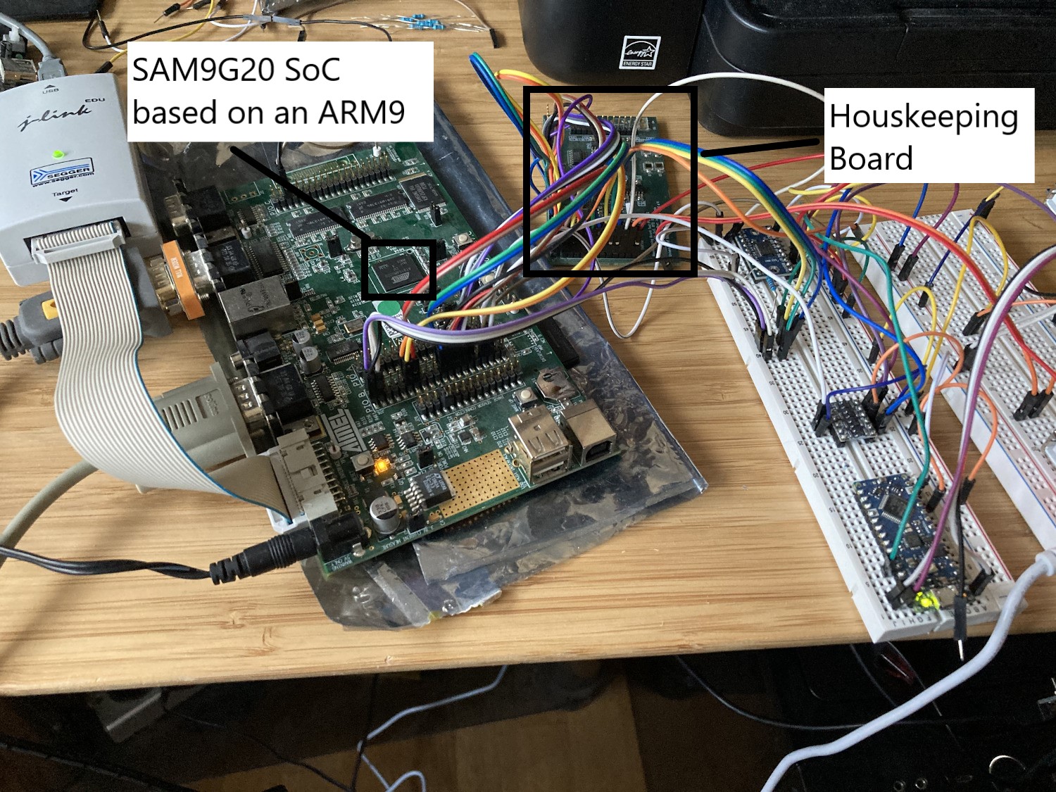
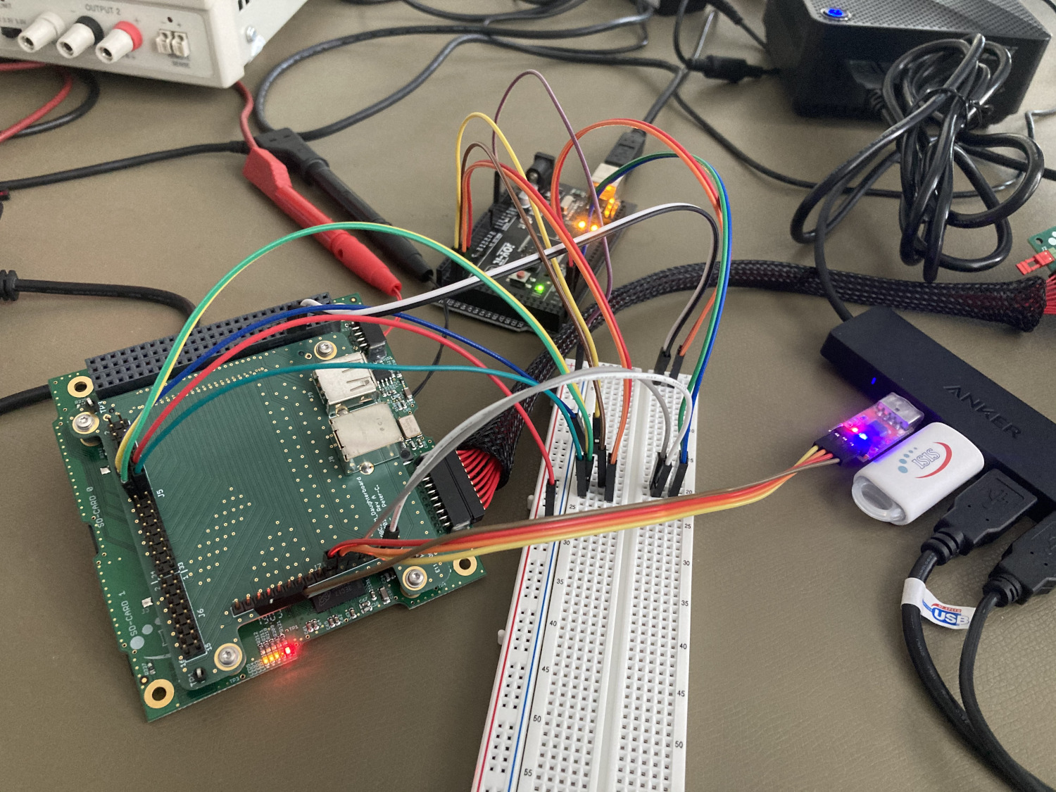
In these difficult times, it is of course better to work for home. After procuring the hardware from the institute, there was the task of setting up the hardware. I focused on two device handlers in particular: The ThermalSensorHandler, which took care of handling a MAX31865 Resistance-to-Digial converter, which in turn was connected to a Pt1000 thermal resistor, and the GyroHandler which handled a BMG250 MEMS gyroscope. Both sensors were soldered on a housekeeping board engineering model (I’d like to thank Jens Polzin, who is designing this board!), which also contains sun sensors and SPI slave select expanders (decoders). The two following pictures show the set-up. The large board on the left is the AT91SAM9G20-EK development board, which has the same chip as the iOBC, which is the on-board computer of the SOURCE project.
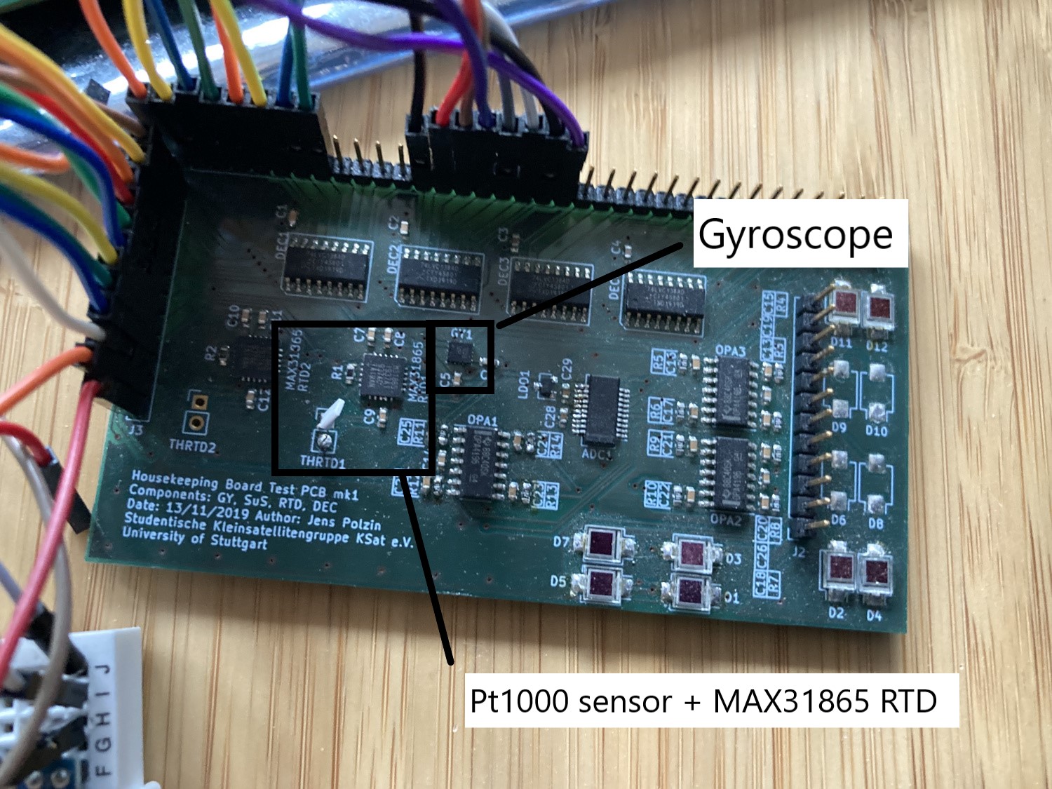
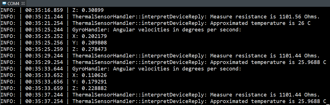
The sensors are generally read and configured by reading certain registers, according to the sensors‘ datasheet. The basic test for the gyro involved taking the housekeeping board (HKB) and rotating it in both directions around every the X, Y and Z axis (kind of like a model airplane). It was also validated that the sensor values show the correct sign when rotating around a certain axis. The basic test for the thermal sensor handler included verifying the approximated temperature (room temperature) and checking whether it rises to 30-31 °C when touching the PT1000 sensor with my fingers .
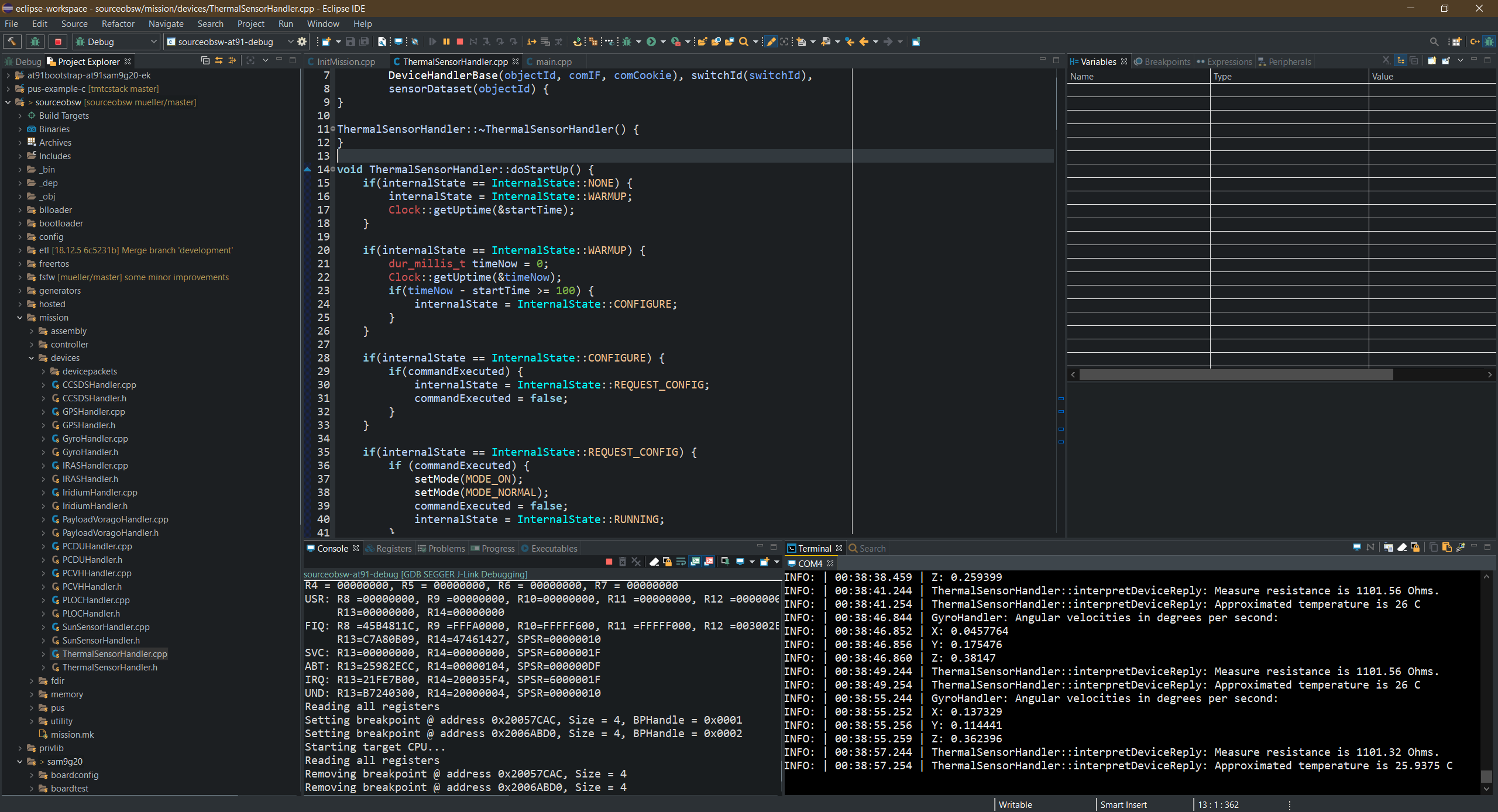
Both device handlers have a start-up sequence which involves configuring the sensor and putting it into a state to perform poll the sensor properly. To perform all the initialization and configuration steps sequentially, an internal state machine is used. The usage of this state machine can be seen throughout the device handler code. The sequence of the device initialization is specified in the doStartUp() abstract function implementation. The specification of the actual commands for start-up, mode transitions or shut-down sequences is specified in the function buildTransitionDeviceCommand() (for simple sensors, this will usually only include the start-up sequence). When the configuration is complete, the device enters the MODE_NORMAL or MODE_ON mode and is ready to poll data. The commands for this nominal operation mode are specified inbuildNormalDeviceCommand(). buildCommandFromCommand() is used to specify commands from external commands (for example, commands coming from ground or from another software component) but is also used by the other command building functions to avoid duplicate code. The functions scanForReply() and interpretDeviceReply() are used to analyse the sensor data and store it into the local datapool for either downlink operation as housekeeping data or for usage by other software components.
On a microcontroller, the print functions generally have to be redirected to a UART peripheral to be sent to the host computer for display. This is used for the AT91. A sample output is show, which shows the two sensors being polled regularly.
I also started to work on a CoreController component, which takes care of monitoring the on-board computer itself. As a first step, I also took all necessary steps to enable communication with the iOBC on-board computer in the clean room of the IRS in Stuttgart. The iOBC engineering model (EM), being a rather expensive piece of hardware which is only available once, will be installed in the clean room and later be integrated into the flatsat, which is one of the most important testing platforms for the satellites and basically includes all the satellites component on a table wired together for testing. Of course, going to the clean room each time just to develop software is a lot of hassle. Therefore, remote development was set-up and is possible via Eclipse and RemoteGDB.
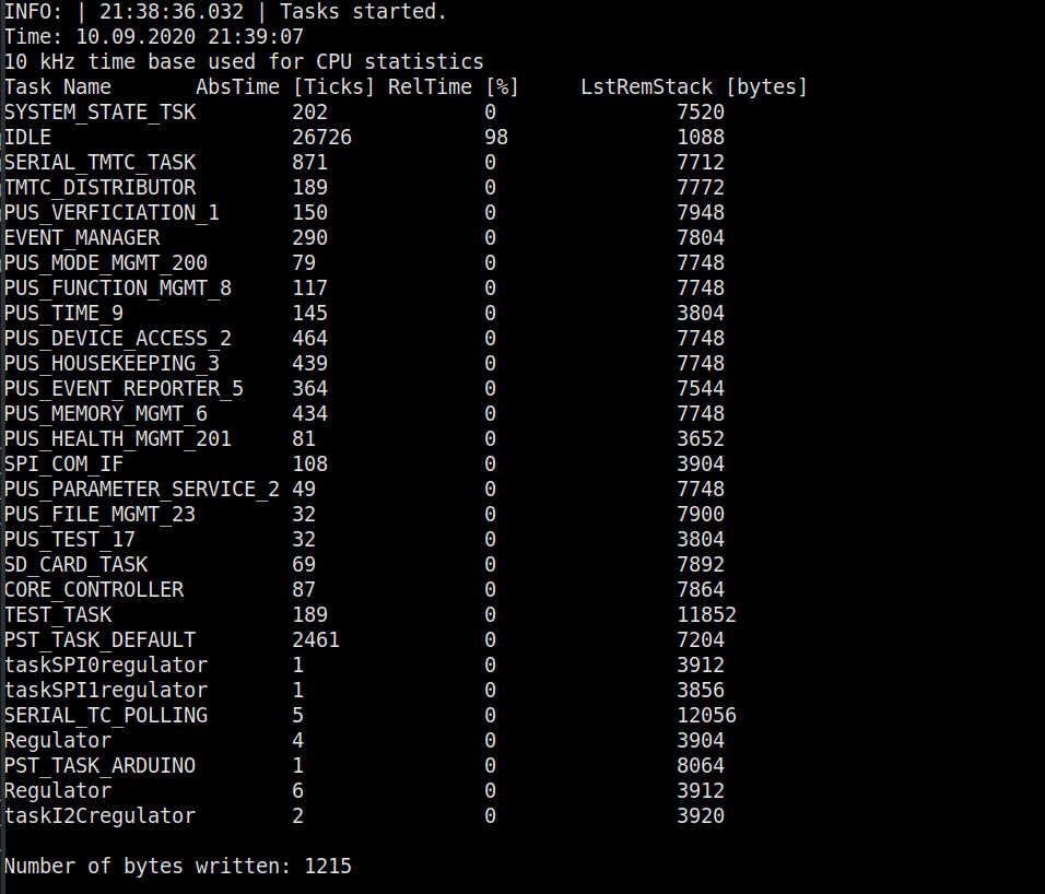
The core controller will take care of monitoring the supervisor, which in turn generates voltage and temperature values of the OBC. It will also take care of monitoring all running tasks. Readers unfamiliar with embedded programming and real-time operating systems propably still understand the concept of threads, which are used extensively on desktop systems. Even though the OBC only has one core, it is possible to perform apparent multitasking by using a scheduler, which is the core component of a real-time operating system (RTOS). The most common ones for space applications among others are FreeRTOS, RTEMS and Linux. The FSFW offers abstraction layers for all of them and FreeRTOS was chosen for SOURCE because the provided driver functions by the OBC manufacturer also use FreeRTOS. The Controller uses the FreeRTOS API to monitor the stack usage of programs, and generate general CPU statistics and downlink them (in CSV format).
Another important task of the core controller is the scrubbing of non-volatile memories on the on-board computer. Space is a hostile environment, and the strong radiation can cause bit flips in the memories, which is also called Single-Event-Upset (SEU). Therefore, a lot of space-grade hardware features advanced error control code (ECC) to correct those anomalies. The OBC of SOURCE does not feature hardware ECC, but it is possible to implement software ECC, for example by using the Hamming Code (https://en.wikipedia.org/wiki/Hamming_code), which is able to correct one bitflip recognize two bitflips per 256 bytes. The hamming code will be generated on ground and written (or uploaded) to the non-volatile memory. It will then be used to regularly check the binaries in the non-volatile memories for bitflips. This task, which is called scrubbing, will also be performed by the core controller.
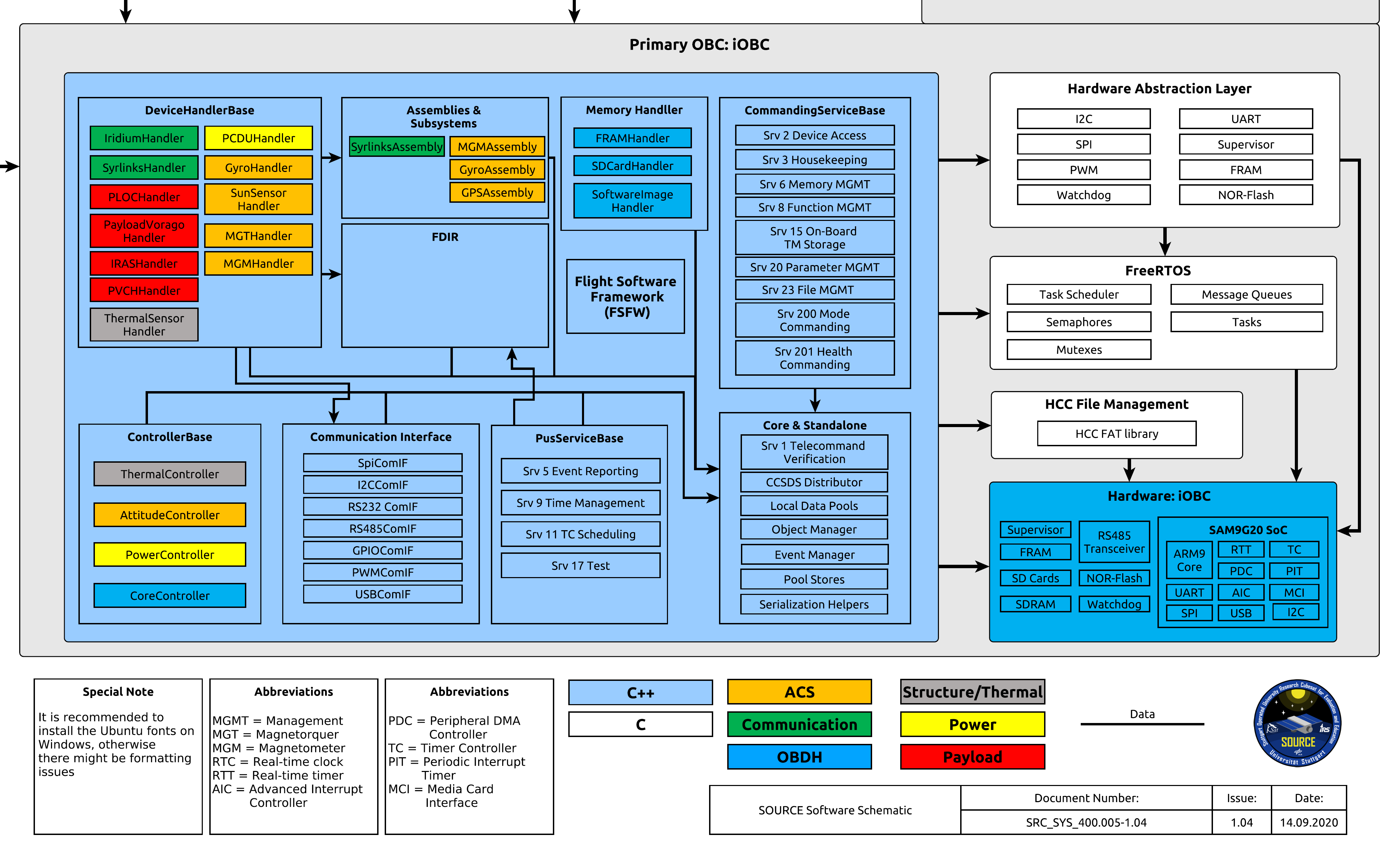
The complexity of the software is quite high. A schematic of the software architecture was created with the graph software yEd to visualize it. This software schematic is the most useful document to show the software architecture in a brief format which is also accessible for other subsystem and stakeholders which are interested in the success of the project. It also exists in similar form to visualize the architecture of the whole system (in therms of hardware).