Previously:
In the previous blog, I penned down a brief introduction to ADS-B(Automatic Dependant Survelliance-Broadcast) and how this project has planned to have all the ground stations self-synchronised.
We now have the main data in our hand :- The ADS-B frames itself! Lets dive deep and see how I am extracting the data and what are the, both normal and non-normal, findings that I’ve made.
Findings
Starting with the first version of the my decoder and data extractor code, I tested it with a rather small, approximately 2 minutes long recording from one of the ground stations.
Before I discuss about what I found in the recording, here is an overview of what I had expected to be present in the recording and what are the capabilities of the current decoder file:
- The structure of a typical ADS-B message with Downlink Format 17 when converted to its binary equivalent.:
| Length | Position | Abbreviation | Name |
|---|---|---|---|
| 5 | 1 – 5 | DF | Downlink Format |
| 3 | 6 – 8 | CA | Capability |
| 24 | 9 – 32 | ICAO | ICAO aircraft address |
| 56 | 33 – 88 | DATA | Data |
| [33 – 37] | [TC] | Type code | |
| 24 | 89 – 112 | PI | Parity/Interrogator ID |
- Length of the messages according to Downlink Format(DF):
- 112 bit (long): DF 16, 17, 18, 19, 20, 21, 22, 24
- 56 bit (short): DF 0, 4, 5, 11
- Not all data is contained in a single message, here’s how to know what data is contained in a particular message based on the Type Code:
| Type Code(TC) | Data |
|---|---|
| 1 – 4 | Aircraft identification |
| 5 – 8 | Surface position | 9 – 18 | Airborne position (Baro Altitude) |
| 19 | Airborne velocities |
| 20 – 22 | Airborne position (GNSS Altitude) |
| 23 – 27 | Reserved |
| 28 | Aircraft status |
| 29 | Target state and status information |
| 31 | Aircraft operation status |
Now, the percentage of each type of message that I found in the recording:
- Aircraft Identifiers: 0.77 %
- Messages with surface position: 0.00 %
- Airborne Position (Barometric Altitude): 8.21 %
- Airborne Velocity messages: 7.60 %
- Airborne Position (GNSS altitude): 0.00 %
- Operation Status messages: 0.82 %
- Enhanced Mode-S ADS-B data: 34.46 %
- Squawk/Ident data: 3.09 %
- Short Air to Air ACAS messages: 14.47 %
- Encoded Altitude only: 29.22 %
- Long ACAS messages: 1.34 %
A total of 13172 messages were detected in this recording.
After a brief analysis what I observed is, the velocity of each aircraft is sent almost after every 4-5 position messages. The reason for the absense of any surface position messages can be that the ground station was not close enough to any airfield. And, by looking at the statistics, usage of barometric altitude seems to be a standard than GNSS altitude.
Decoding the Data
Our prime point of focus are the Airborne Position messages (DF 17-18, TC 9-18) as the title of the project suggests. Let’s discuss about how my code goes about decoding the location from each frame.
Pre-Step : Creating ‚identifier‘ functions which determines the message type. One such identifier function would be an ‚Airborne Position‘ message identifier.
Typical structure of an ‚Airborne Position‘ Message is given as:
| Position | Position in Data block | Bit Length | Content |
|---|---|---|---|
| 33 – 37 | 1 – 5 | 5 | Type code |
| 38 – 39 | 6 – 7 | 2 | Surveillance status |
| 40 | 8 | 1 | NIC supplement-B |
| 41 – 52 | 9 – 20 | 12 | Altitude |
| 53 | 21 | 1 | Time |
| 54 | 22 | 1 | CPR odd/even frame flag |
| 55 – 71 | 23 – 39 | 17 | Latitude in CPR format | 72 – 88 | 40 – 56 | 17 | Longitude in CPR format |
There are two methods of determining the location:
- Globally Unambiguous method: This method requires two frames for the calculation. The frames should be a pair of an odd frame and an even frame, received in succession. Two even frames or two odd frames will not work in this method.
Bit-54 in the binary equivalent of the message is the flag bit that tells us whether the frame is even or odd.
0 – Even Frame
1 – Odd Frame
Bits 55-71 contain latitude in CPR format, and bits 72-88 contain longitude in CPR format. Thus the CPR is calculated by
LAT_CPR = decimal(bits 55-71) / 131072
LON_CPR = decimal(bits 72-88)/ 131072
The decimal equivalent of the CPR is encoded in 17 bits. So the maximum value that it can have is 2^17 or 131072, thus the CPR is mapped to a floating value below 1 by dividing it by 131072.
Calculation of Latitude:
Latitude Index(j):
We need two constants to compute the relative latitudes
Where NZ is the abbreviation of number of geographic latitude zones present between the equator and the poles. NZ = 15 is a standard for Mode-S position encoding.
Thus, the calculation of the relative latitude coordinate:
For locations in southern hemisphere, the latitude lies between 270 – 360 degrees, but we need to restrict the range to [-90, 90]
The final latitude is chosen based on the newest frame received. If the newest received frame has an even CPR flag, then the even latitude (LatEven) will be the final latitude and vice-versa.
We now have one coordinate in our hand !!
Before we place foot in computing the longitude, we should check if both the latitudes in the two frames are consistent, i.e. they lie in the same latitude zone
- Check for Latitude zone consistency:
Let’s define a function which returns the number of latitude zones. ‚NL(latitude)‘ is how it is named.
NL():
The returned value lies in the closed interval [1, 59]
Both the calculated latitude of the even and the odd frames are passed to this function, if the returned value is equal for both the cases, then both of them lies in the same zone, and the code has successfully removed the ambiguity in them.
If the returned values are unequal, then skip the calculation and wait for a new message.
Calculation of Longitude:
If the newer message among the pair of frames is even:
When the newer message to be received is odd:
For both cases, if Lon is greater than 180 degrees
Now we have the coordinates of the aircraft (lat, lon) calculated using the ‚Globally unambiguous method‘
- Locally unambiguous method:
This method requires a reference location for calculation. This location must be within 180NM from the location to be calculated.
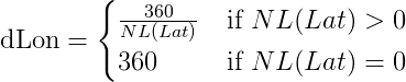
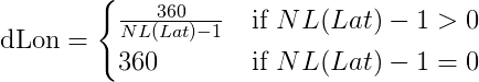
Calculation of dLon
Latitude index (j):
Latitude is thus given by:
Calculation of longitude:
Here NL function is the same as it has been defined for the 'Globally Unambiguous method'.
Longitude index (m):
Thus, longitude is given by:
- Calculation of Altitude:
Bits 41-52 contain the altitude in a DF 17 TC 9-18 ADS-B frame
Bit 48 is known as the Q-Bit which determines the encoding multiple of the altitude
If Q-Bit = 1; 25 feet
else if Q-Bit = 0; 100 feet
The binary string spans from bit 41-52 excluding Q-bit(48)
Thus the Altitude is given by:
Where N is the decimal equivelent of bit 41-52 excluding the Q-bit
It was now time to execute this implementation !!
And here are the first set of results:
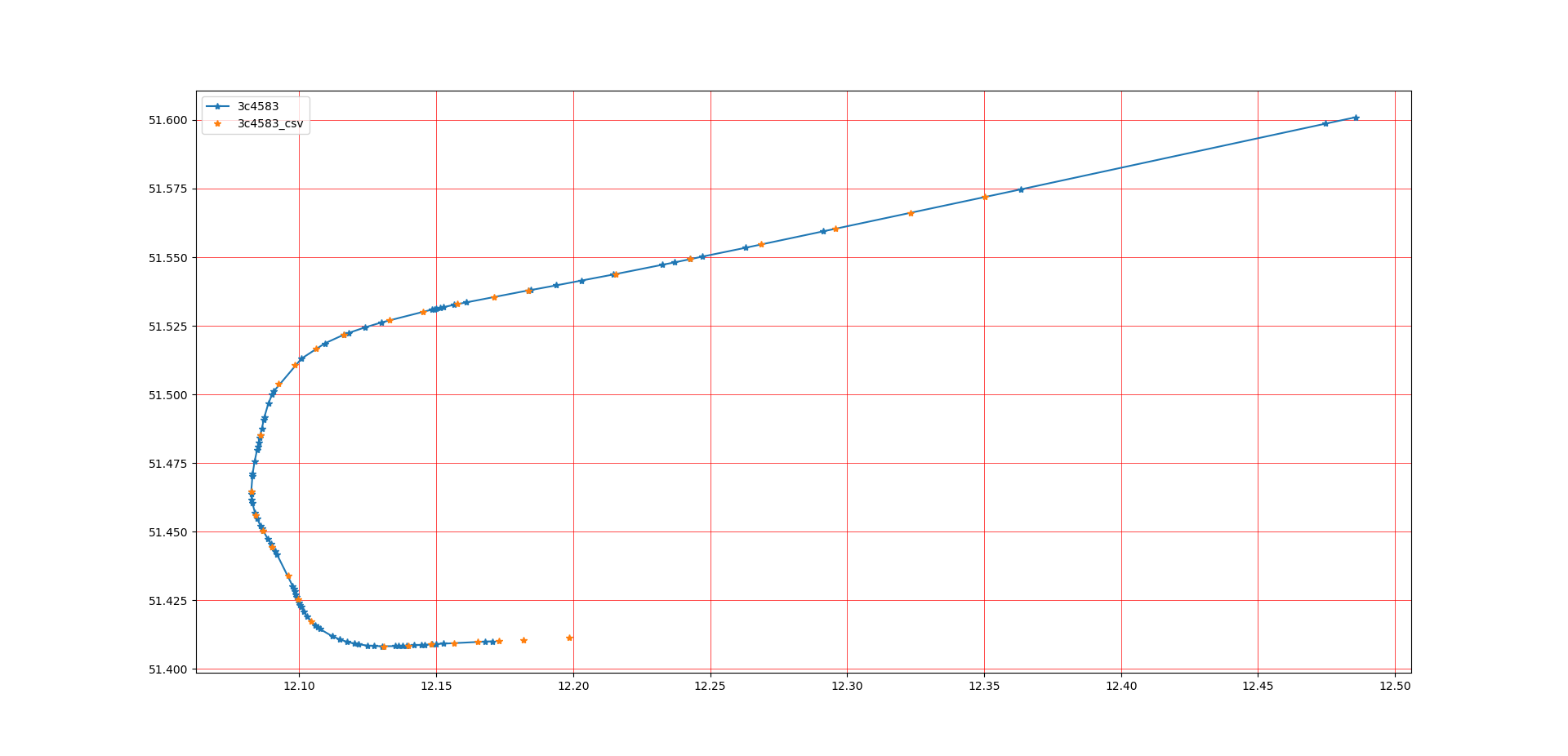
The blue plots are the locations calculated by the current code.
Whereas, the yellow plots are the ones obtained from other sources.
The 3rd party sources do not give us with raw calculated data, that's why the plots do not match even though the flight path overlaps.
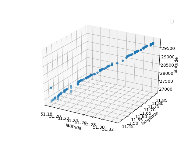
Here is a plot where you can identify a cruising aircraft:
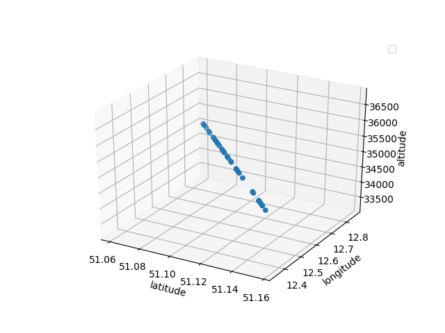
And also an aircraft which is beginning is decent towards Leipzig Airport:
Unusual findings:
The first stage of the code where I had implemented the decoding of position only by ‚Globally Unambiguous Method‘, I found a few stray points in the plots. A good term for this would be removal of ‚Vomit Comets‘. For example:
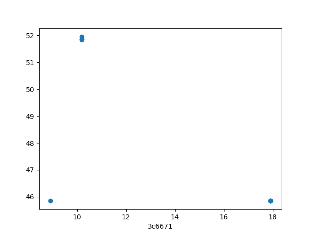
As you can see, it does not define a proper flight path.
Here, I now introduce a checking system, where the position of the newest frame is calculated using the ‚Locally unambiguous method‘ and it then compares both the positions.
If there is a difference, then the position calculated by the latter method is taken as ultimate.
Also, many singular frames were skipped from the intial position calculation logic as there wasn’t a compatible succesive frame. For them, the location calculated by the latter method was final.
Up Next:
I will dig further into how I am decoding and calculating other flight parameters such as, airspeed, ground speed, heading, aircraft identify codes (such as SQUAWK and Callsign).
Also, the initial phases after the completion of the decoding layer: Searching of overlapping files from different ground stations.
Feel free to get in touch with me:
- https://twitter.com/shoumik_dey
- https://github.com/shoumikdey
- shoumik.dey@aerospaceresearch.net