This Project for this year’s edition of Google Summer of Code was titled: Decoding of ADS-B(Automatic dependent surveillance—broadcast)and Multi-lateralPositioning.
The aim of the project is to decode ADS-B frames/messages from raw IQ streams recorded using RTL-SDR radios and extract the data from these frames such as aircraft identifications, position, velocity, altitude etc.
The next part is to find the location of an aircraft when it sends a frame not having any position data in it’s payload using multilateration.
What is Multilateration ?
Multilateration is a method by which the location of an aircraft (can be any moving object which broadcasts a signal) using multiple ground stations and the Time Difference of Arrival(TDOA) of a signal to each ground station.
Implementations
Identification of long(112 bit) and short(56 bit) frames.
With the long frames, identifying each type of frame and the data contained in it.
Decoding and extracting the available data in the payload according to the frame type.
Building and outputting JSON files containing ADS-B frames and decoded data. (Gzipped)
Loading of files from multiple stations simultaneously.
Checking and grouping files which were recorded during the same time or have overlapping recording intervals.
Searching unique signals/frames in the overlapping files across different stations.
Testing
Since, position is one of the key component to this project, the first phase of testing was aimed at finding any hidden logical bugs in the code which calculates the position from the position containing frames.
As mentioned in the previous blogs, two methods are used to calculate the location.
The result obtained:
The plots in ‚yellow‘ are obtained from 3rd party trusted sources. This is a comparison plot of ‚our‘ output with trusted sources.
The project is expected to process files from several stations (5 stations) together. Thus there was a requirement to find files from different ground stations which were recorded at the same time interval. It can also be that the a part of the file overlaps. After which the ‚unique‘ frames were searched in these files.
The file overlap checker was tested with recordings from 5 stations recorded on 16th February in Germany.
This test run could find ‚unique‘ frames which were occuring atmost thrice, present at different ground stations.
Foremost, I would like to extend my sincere gratitude to my mentor and organisation head Andreas Hornig, for mentoring me throughout the season. Since I am not pursing a major in Computer Science altough coding and so called ‚cool stuffs‘ is my second hobby and passion, I would also like to appreaciate the additional energy and effort he has put in guiding me.
Besides, I put forth my vote of thanks to the organisation (Aerospaceresearch.net) as a whole, all the other mentors and the fellow students for making this organisation what it is and providing me with the opportunity to work on an open-source project.
I discussed about how I am decoding the position of the aircraft from 2 ADS-B frames and also from 1 ADS-B frame and a reference position and how I found both handsome and erractic readings.
Let’s look into how other airborne parameters, such as ‚aircraft identity‘ and ‚velocity‘ are being decoded and calculated.
There is a special type of frame which is known as ‚Enhanced Mode-S‘ frames. They also contain similar information at times like the non-Enhanced Mode-S frames. I will elaborate on both in this blog.
Frames with downlink format 20 & 21 are known as Enhanced Mode-S frames.
The following methods were implemented in the code for decoding the information from the ADS-B frames.
Aircraft Identification
Frames with Downlink Format 17-18 and Type Code 1-4 are known as aircraft identification messages.
The structure of the 56-bit DATA field of any such aircraft identification frame will be as follows:
TC
EC
C1
C2
C3
C4
C5
C6
C7
C8
5
3
6
6
6
6
6
6
6
6
TC: Type Code
EC: Emitter Code
Second row signifies the bit-length
The EC value with regard to the TC value determines the type of aircraft (Such as : Super, Heavy, light etc). When the EC is set to ‚zero‘ signifies such information is not being transmitted by the aircraft.
An Airbus A380 is known as 'Super' and a Boeing 777-300ER is known as 'Heavy'. Small, private or training aircrafts such as Cessna 172s are known as 'Light'.
For determining the callsign a lookup table is used:
‚#‘ signifies a null value and ‚_‘ signifies a space between two words.
Let us take an Aircraft identifier frame recorded by one of our ground stations:
a0001910200490f1df2820700716
Thus the DATA part of this frame is:
200490f1df2820
BIN
00100000
000001
001001
000011
110001
110111
110010
100000
100000
INT
4
1
9
3
49
55
50
32
32
CHAR
[TYPE CODE]
A
I
C
1
7
2
_
_
The integer number corresponds to the corresponding element in the lookup table array.
Thus, the decoded callsign is „AIC172“ which belongs to Air India on the route 172
BDS 2,0 frames are also known as Aircraft Identification Messages. In these frames the first 8 bit of the DATA segment contains the BDS number and the rest is same as the previous one.
Airborne Velocity
ADS-B frames with Downlink Format 17-18 and TC 19 contain the velocity information of the aircraft.
Subtype 1 (Ground Speed)
The typical structure of the frame:
Position in frame
Position in data block
Length
Abbreviation
Data
33 – 37
1 – 5
5
TC
Type code
38 – 40
6 – 8
3
ST
Subtype
41
9
1
IC
Intent flag
42
10
1
RESV_A
Reserved-A
43 – 45
11 – 13
3
NAC
Velocity uncertainty (NAC)
46
14
1
S_ew
East-West velocity sign
47 – 56
15 – 24 change
10
V_ew
East-West velocity
57
25
1
S_ns
North-South velocity sign
58 – 67
26 – 35
10
V_ns
North-South velocity
68
36
1
VrSrc
Vertical rate source
69
37
1
S_vr
Vertical rate sign
70 – 78
38 – 46
9
Vr
Vertical rate
79 – 80
47 – 48
2
RESV_B
Reserved-B
81
49
1
S_Dif
Diff from baro alt, sign
82 – 88
50 – 56
7
Dif
Diff from baro alt
These two bits determine the direction at which the aircraft was flying:
S_ns:
     1 -> flying North to South
     0 -> flying South to North
 S_ew:
     1 -> flying East to West
     0 -> flying West to East
The speed and the heading can thus be computed by:
If the calculated heading is negative, then we add 360 to it.
Vertical Speed
The S_Vr bit (69) determines the direction(ascent/descent).
0- Up
1- Down
Therefore the actual speed is calculated by:
V = (int(Vr) – 1) * 64
Therefore, V is the speed and S_Vr states whether the aircraft is climbing or descending.
The VrSrc field (Vertical Rate Source) determines the measured altitude type:
Here let us see how the structure of Subtype 3 differs from Subtype1:
Position in frame
Position in data block
Length
Abbreviation
Data
33 – 37
1 – 5
5
TC
Type code
38 – 40
6 – 8
3
ST
Subtype
41
9
1
IC
Intent change flag
42
10
1
RESV_A
Reserved-A
43 – 45
11 – 13
3
NAC
Velocity uncertainty (NAC)
46
14
1
S_hdg
Heading status
47 – 56
15 – 24
10
Hdg
Heading (proportion)
57
25
1
AS-t
Airspeed Type
58 – 67
26 – 35
10
AS
Airspeed
68
36
1
VrSrc
Vertical rate source
69
37
1
S_vr
Vertical rate sign
70 – 78
38 – 46
9
Vr
Vertical rate
79 – 80
47 – 48
2
RESV_B
Reserved-B
81
49
1
S_Dif
Difference from baro alt, sign
82 – 88
50 – 66
7
Dif
Difference from baro alt
Heading
The S_hdg bit shows whether heading data is available or not:
0 - Heading data not available
1 - Heading data available
If heading data is available then it is calculated by:
Heading = Hdg(10 bit data) * 360/1024
Velocity (Airspeed)
Simply converting the AS bits gives the airspeed in knots.
Vertical Rate is calculated in the same manner as in Subtype 1
Enhanced Mode-S:
Aircraft Intention (BDS4,0)
The structure:
Field
Position
Length
Status
1
1
MCP selected altitude Precision = 16ft
2-13
12
Status
14
1
FMS selected altitude Precision = 16ft
15-26
12
Status
27
1
Barometric setting (in mb and not hPa) Value is actual minus 800 Precision = 0.1mb
28-39
12
Reserved
40-47
8
Status
48
1
VNAV hold state
49
1
ALT hold state
50
1
APP hold state
51
1
Reserved
52-53
2
Status
54
1
Altitude source: 00: Unknown 01:Aircraft altitude 10: MCP set altitude 11: FMS set altitude9
55-56
2
Note: MCP stands for Mode Control Panel where the pilot feeds in the data to the autopilot
FMS stands for Flight Management Computer where the data is fed to calculate various other flight parameters.
Track and Turn (BDS 5,0):
Many more information is given such as roll angle, true track angle etc:
Field
Position
Length
Status
1
1
Sign, 1
1
1
Roll angle range = [-90, 90] degrees Precision = 45/256 degree
3-11
9
Status
12
1
Sign
13
1
True Track angle Precision: 90/512 degree-
14-23
10
Status
24
1
Ground Speed Precision: 2 knots
25-34
10
Status
24
1
Sign
36
1
Track angle rate Precision: 8/256 degree/second
37-45
8
Status
46
1
True Airspeed Precision: 2 knots
47-56
10
Note: The sign bit determines whether to use 2's complement to determine the value present after it. It it is set to '1' then we have to use 2's complement.
Airspeed and Heading (BDS 6,0)
A lot more information is conveyed in this kind of frames:
Unfortunately the percentage of decodable Enhanced Mode-S message received was very low in both short recordings and long recordings which was worth hours.
File overlap checker:
The ground stations were programed to span each recorded file for 2 minutes(approx.). Now this means that for a long duration, there will be an array of files from several ground stations.
There has to be a logic, where the code finds all the files from several ground stations recorded at the same or has overlapping recording times and club them together for the next step.
I identified few such cases of overlaps:
The overlapping files are clubbed together into a list for further processing.
Next step is to find the same frames present in different station recordings, so we need to know the files that overlap and process it accordingly.
In the previous blog, I penned down a brief introduction to ADS-B(Automatic Dependant Survelliance-Broadcast) and how this project has planned to have all the ground stations self-synchronised.
We now have the main data in our hand :- The ADS-B frames itself! Lets dive deep and see how I am extracting the data and what are the, both normal and non-normal, findings that I’ve made.
Findings
Starting with the first version of the my decoder and data extractor code, I tested it with a rather small, approximately 2 minutes long recording from one of the ground stations.
Before I discuss about what I found in the recording, here is an overview of what I had expected to be present in the recording and what are the capabilities of the current decoder file:
The structure of a typical ADS-B message with Downlink Format 17 when converted to its binary equivalent.:
Length
Position
Abbreviation
Name
5
1 – 5
DF
Downlink Format
3
6 – 8
CA
Capability
24
9 – 32
ICAO
ICAO aircraft address
56
33 – 88
DATA
Data
[33 – 37]
[TC]
Type code
24
89 – 112
PI
Parity/Interrogator ID
Length of the messages according to Downlink Format(DF):
112 bit (long): DF 16, 17, 18, 19, 20, 21, 22, 24
56 bit (short): DF 0, 4, 5, 11
Not all data is contained in a single message, here’s how to know what data is contained in a particular message based on the Type Code:
Type Code(TC)
Data
1 – 4
Aircraft identification
5 – 8
Surface position
9 – 18
Airborne position (Baro Altitude)
19
Airborne velocities
20 – 22
Airborne position (GNSS Altitude)
23 – 27
Reserved
28
Aircraft status
29
Target state and status information
31
Aircraft operation status
Now, the percentage of each type of message that I found in the recording:
Aircraft Identifiers: 0.77 %
Messages with surface position: 0.00 %
Airborne Position (Barometric Altitude): 8.21 %
Airborne Velocity messages: 7.60 %
Airborne Position (GNSS altitude): 0.00 %
Operation Status messages: 0.82 %
Enhanced Mode-S ADS-B data: 34.46 %
Squawk/Ident data: 3.09 %
Short Air to Air ACAS messages: 14.47 %
Encoded Altitude only: 29.22 %
Long ACAS messages: 1.34 %
A total of 13172 messages were detected in this recording.
After a brief analysis what I observed is, the velocity of each aircraft is sent almost after every 4-5 position messages. The reason for the absense of any surface position messages can be that the ground station was not close enough to any airfield. And, by looking at the statistics, usage of barometric altitude seems to be a standard than GNSS altitude.
Decoding the Data
Our prime point of focus are the Airborne Position messages (DF 17-18, TC 9-18) as the title of the project suggests. Let’s discuss about how my code goes about decoding the location from each frame.
Pre-Step : Creating ‚identifier‘ functions which determines the message type. One such identifier function would be an ‚Airborne Position‘ message identifier.
Typical structure of an ‚Airborne Position‘ Message is given as:
Airborne position message bits explained
Position
Position in Data block
Bit Length
Content
33 – 37
1 – 5
5
Type code
38 – 39
6 – 7
2
Surveillance status
40
8
1
NIC supplement-B
41 – 52
9 – 20
12
Altitude
53
21
1
Time
54
22
1
CPR odd/even frame flag
55 – 71
23 – 39
17
Latitude in CPR format
72 – 88
40 – 56
17
Longitude in CPR format
There are two methods of determining the location:
Globally Unambiguous method: This method requires two frames for the calculation. The frames should be a pair of an odd frame and an even frame, received in succession. Two even frames or two odd frames will not work in this method.
Bit-54 in the binary equivalent of the message is the flag bit that tells us whether the frame is even or odd.
0 – Even Frame
1 – Odd Frame
Bits 55-71 contain latitude in CPR format, and bits 72-88 contain longitude in CPR format. Thus the CPR is calculated by
LAT_CPR = decimal(bits 55-71) / 131072
LON_CPR = decimal(bits 72-88)/ 131072
The decimal equivalent of the CPR is encoded in 17 bits. So the maximum value that it can have is 2^17 or 131072, thus the CPR is mapped to a floating value below 1 by dividing it by 131072.
Calculation of Latitude:
Latitude Index(j):
We need two constants to compute the relative latitudes
Where NZ is the abbreviation of number of geographic latitude zones present between the equator and the poles. NZ = 15 is a standard for Mode-S position encoding.
Thus, the calculation of the relative latitude coordinate:
For locations in southern hemisphere, the latitude lies between 270 – 360 degrees, but we need to restrict the range to [-90, 90]
The final latitude is chosen based on the newest frame received. If the newest received frame has an even CPR flag, then the even latitude (LatEven) will be the final latitude and vice-versa.
We now have one coordinate in our hand !!
Before we place foot in computing the longitude, we should check if both the latitudes in the two frames are consistent, i.e. they lie in the same latitude zone
Check for Latitude zone consistency:
Let’s define a function which returns the number of latitude zones. ‚NL(latitude)‘ is how it is named.
NL():
The returned value lies in the closed interval [1, 59]
Both the calculated latitude of the even and the odd frames are passed to this function, if the returned value is equal for both the cases, then both of them lies in the same zone, and the code has successfully removed the ambiguity in them.
If the returned values are unequal, then skip the calculation and wait for a new message.
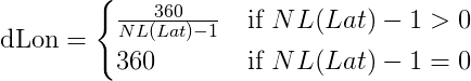
Calculation of Longitude:
If the newer message among the pair of frames is even:
When the newer message to be received is odd:
For both cases, if Lon is greater than 180 degrees
Now we have the coordinates of the aircraft (lat, lon) calculated using the ‚Globally unambiguous method‘
Locally unambiguous method:
This method requires a reference location for calculation. This location must be within 180NM from the location to be calculated.
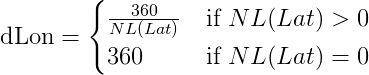
Calculation of dLon
Latitude index (j):
Latitude is thus given by:
Calculation of longitude:
Here NL function is the same as it has been defined for the 'Globally Unambiguous method'.
Longitude index (m):
Thus, longitude is given by:
Calculation of Altitude:
Bits 41-52 contain the altitude in a DF 17 TC 9-18 ADS-B frame
Bit 48 is known as the Q-Bit which determines the encoding multiple of the altitude
If Q-Bit = 1; 25 feet
else if Q-Bit = 0; 100 feet
The binary string spans from bit 41-52 excluding Q-bit(48)
Thus the Altitude is given by:
Where N is the decimal equivelent of bit 41-52 excluding the Q-bit
It was now time to execute this implementation !!
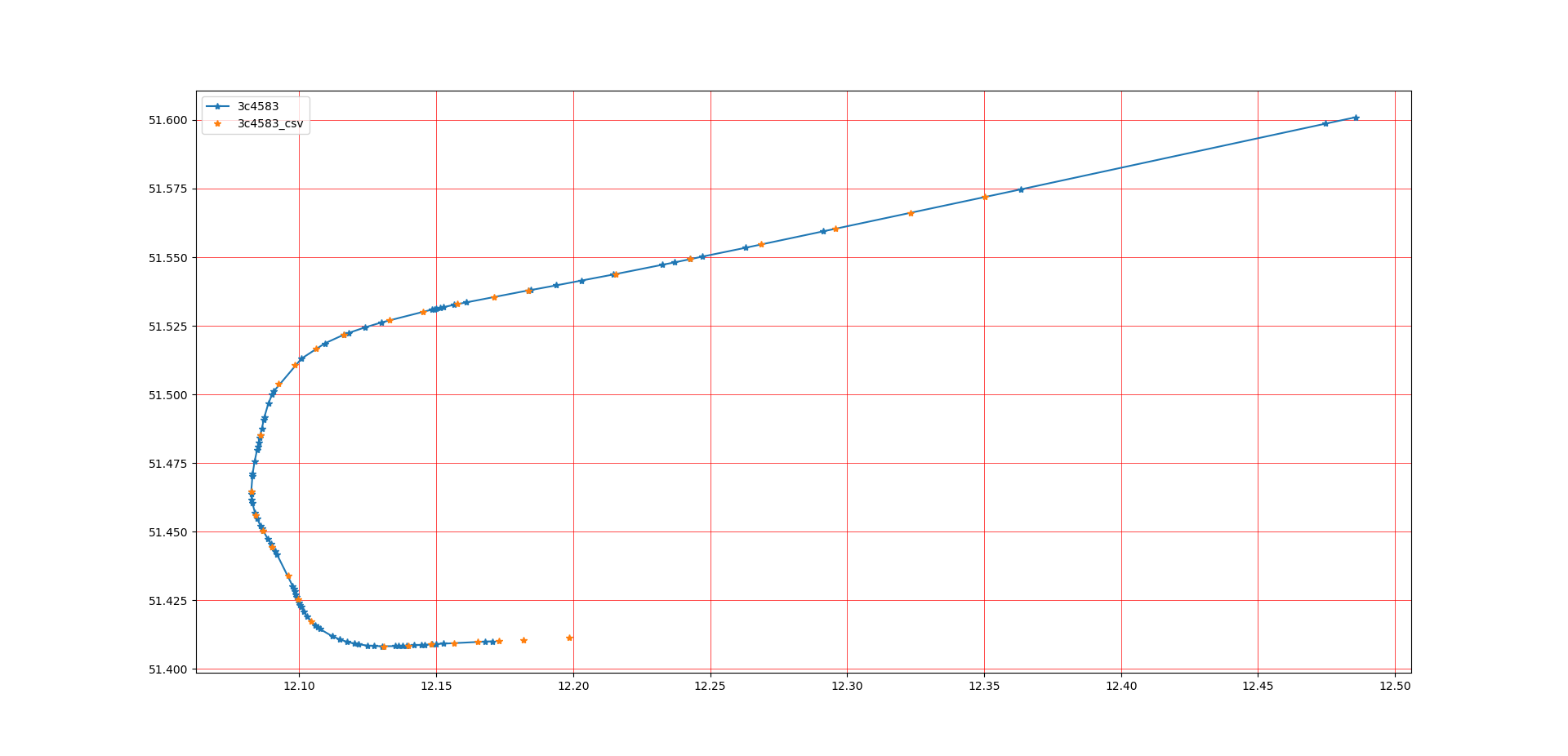
And here are the first set of results:
Here is a comparison of the results obtained from my code and data acquired from trusted 3rd party sources
The blue plots are the locations calculated by the current code.
Whereas, the yellow plots are the ones obtained from other sources.
The 3rd party sources do not give us with raw calculated data, that's why the plots do not match even though the flight path overlaps.
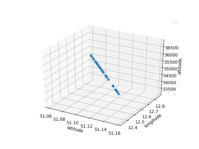
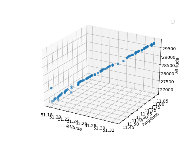
Here is a plot where you can identify a cruising aircraft:
And also an aircraft which is beginning is decent towards Leipzig Airport:
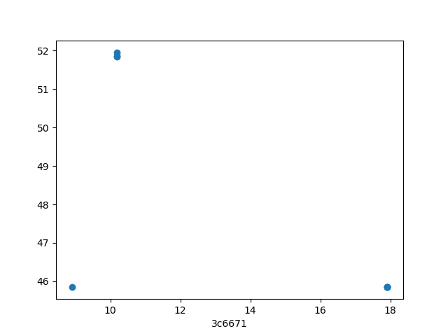
Unusual findings:
The first stage of the code where I had implemented the decoding of position only by ‚Globally Unambiguous Method‘, I found a few stray points in the plots. A good term for this would be removal of ‚Vomit Comets‘. For example:
As you can see, it does not define a proper flight path.
Here, I now introduce a checking system, where the position of the newest frame is calculated using the ‚Locally unambiguous method‘ and it then compares both the positions.
If there is a difference, then the position calculated by the latter method is taken as ultimate.
Also, many singular frames were skipped from the intial position calculation logic as there wasn’t a compatible succesive frame. For them, the location calculated by the latter method was final.
Up Next:
I will dig further into how I am decoding and calculating other flight parameters such as, airspeed, ground speed, heading, aircraft identify codes (such as SQUAWK and Callsign).
Also, the initial phases after the completion of the decoding layer: Searching of overlapping files from different ground stations.
My name is Shoumik Dey. I am currently a second year student at Manipal Institute of Technology, India. I preserve strong interest in aviation, aeromodelling and maybe this is the reason that I have chosen to work on this project, this summer, for Google Summer of Code 2019.
This is the first blog post for this project. This post will describe the work done so far, the current outcomes, hurdles faced and also they were/can be be solved.
Introduction
‚ADS-B‘ stands for Automatic Dependent Surveillance–Broadcast. The aircraft automatically brodcasts each frame on the 1090MHz frequency periodically which contains navigational data, such as, location, altitude, airspeed etc.
All ADS-B frames do not contain location information in them, therefore the ultimate goal of this project can be described in two parts:
Self-syncronisation of the ground stations in focus without an external agent.
Determining the location of the aircraft when location data is not received using multi-lateral positioning
Self-synchronisation
The current and widely used method of synchronising the clock of any ground based station is by using GNSS(Global Navigation Satellite System)-receiver interrogation. The local clocks gets aligned with the atomic clocks in the satellite.
But in this case, the synchronisation takes place by calculating the actual point of time when an aircraft broadcasts a message. This serves as the reference time at all ground stations, and since this time value is same all over, hence all the stations become self-synchronised.
Data required for self synchronisation:
Time of arrival of the message at the ground station
Time difference of arrival at that station.
Calculating the time difference of arrival(TDOA):
The receiver provides the time at which the frame(with location) is received.
The time of travel of the frame is calculated by using simple math and that is subtracted from the time of arrival.
sqrt((x2-x1)^2 + (y2 - y1)^2 + (z2 - z1)^2)
where x1, y1, z1: Latitude, longitude and altitude of ground station; x2, y2, z2: Latitude, longitude and altitude reported by aircraft.
Data that we have for self-synchronisation:
We have decided on using dump1090 for generating the ADS-B messages from the IQ stream as recorded by the SDR radio. Dump1090 provides the mlat(multilateration) data in avr format. The first 6 bytes of the message provides the sample position of the last bit of that message.
Next, we shift the sample position record from the last bit of the message to the first bit.
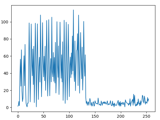
Typical recording of a 112 bit ADS-B messageTypical recording of a 56 bit ADS-B message
As we can see, the length of the messages is exactly half of each other.
The sample position reported by dump1090 is exactly 240 samples ahead of the preamble (You can see the preamble at the beginning, by 4 spikes in the signal).
So, the sample position is taken back by 240 samples for both the cases to reach the beginning of the preamble.
Now, data in hand:
Start time of the stream
Sample position of the beginning of the message in the stream.
Therefore the time of arrival(TOA) can thus be calcualted.
Work done so far
A plugin to import the mlat output of dump1090 (ADS-B raw) has been created, which imports the message and the sample position into the main program
The raw data is reorganised in our suitable format and terms.
With each frame present;( for 112 bit frames as of now)
Determination of the type of frame and it’s content
Decoding those data present in that frame
Output dump file which contains the frame and the data contained in it. (Only extraction, no calcualation)
Next up….
The next blog post will contain the implementation of the calculation layer of the project. In this layer, the data in the frames will be processed and information such as position, velocity, altitude will be covered.
The post will also contain the unusual findings and irregularities that were found in the stream and how we have decided to deal with it.