Many modern communication systems are moving away from traditional analog communication methods to digital communication systems. Using a digital system makes the communication more robust, however will make the system complicated. In this blog we will look at the PSK (Phase shift keying) modulation, specifically QPSK and BPSK.
Many modern satellites use these methods of modulation to transmit data. Some of our satellites of interest are the Meteor satellites (similar to NOAA KLM weather satellites) with higher resolution images and more channels, which uses QPSK. We are also interested in cubesats like Funcube which use BPSK. Hence we are exploring the ways of demodulating and decoding these signals and implementing in our software.
What is PSK?
PSK or Phase Shift Keying, as the name suggests, a modulation method in which the information is encoded within the phase of the carrier wave.
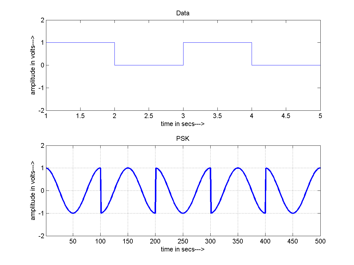
![PSK [1]](https://in.mathworks.com/matlabcentral/mlc-downloads/downloads/submissions/36072/versions/1/screenshot.png)
Similarly if we chose to have 4 such different phases, we could transmit log2(4) = 2 bits of information every symbol. This is called QPSK. Similarly many more such modulation schemes exist.
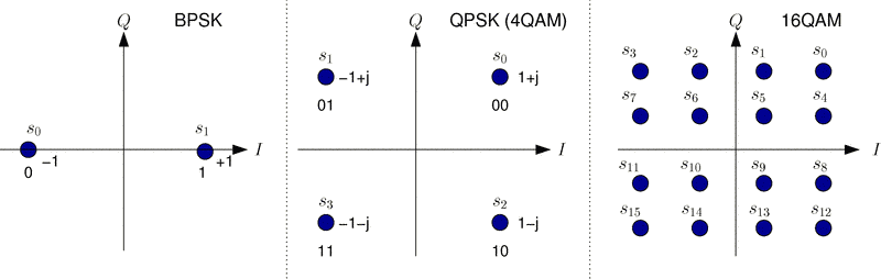
Constellation diagram
Constellation diagrams are usually used to represent these modulation schemes. These diagrams can show us how many phases are possible and how they are spaced.
How is the demodulation done?
Since the data is stored in the phase of the received carrier wave, we will have to find the phase of the wave at different points in time and use that to determine the bits being sent. The basic idea is to multiply the modulated wave with the carrier wave again to get back information about the phase. Since due to various reasons (doppler, noise, phase error, freq error etc.) a constant oscillator is not used. A PLL is used to lock on to the received signal and recover the carrier, this is called carrier recovery. Then this dynamically adjusting wave is used to determine the phase differences. In order to determine the proper time for sampling the symbol to draw the constellation, Gardner’s algorithm is used.
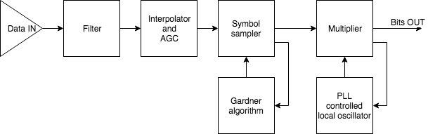
In the above block diagram we show the basic implementation of this. First the signal is filtered to remove the added gaussian noise. Then the sampling frequency is modified to suite our needs. Then an AGC is used to make sure that the signal always has a reasonable amplitude. Then the gardner’s algorithm loop is used to determine the appropriate time for sampling. This makes sure that the symbols are appropriately sampled and given to the PLL. Next, the Costa’s loop multiplies the sampled point to get the bits, then adjusts the PLL variables, in essence doing carrier recovery. After the multiplication, the obtained value is used to determine the bits being sent. Basically the closest point in the constellation is the bit combination.
Results
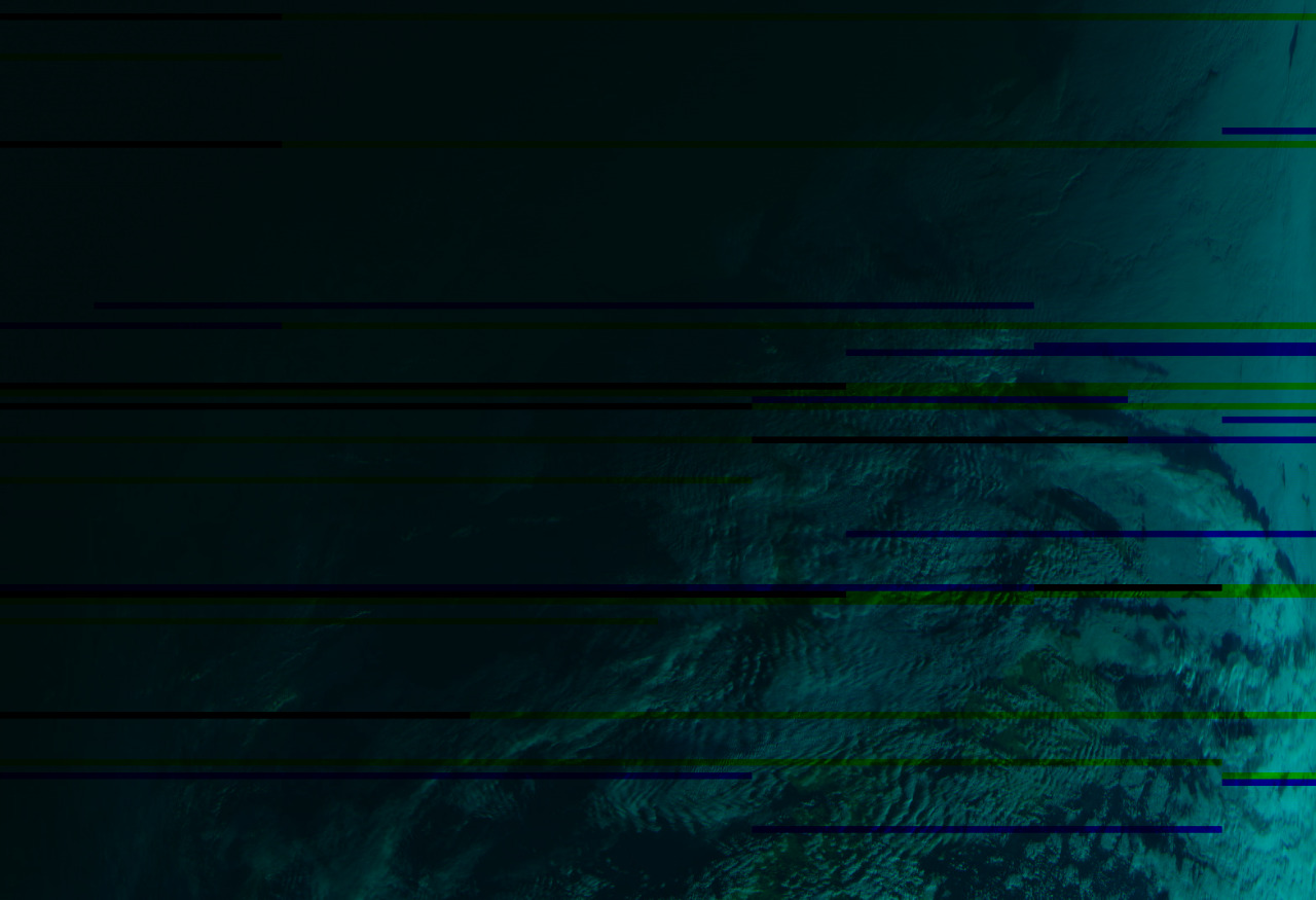
We used this to demodulate the Meteor M2 QPSK signal. The obtained constellation is as follows.
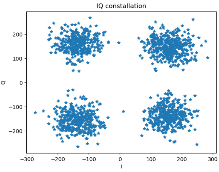
One can observe that this forms four clusters, as we expect in a QPSK system. Using the decoded bits we were able to get the following image being sent by the satellite.
Further, signals from Funcube were demodulated to get the following constellation.
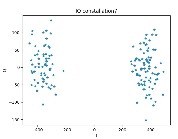
In this, we can clearly see a cluster of two as expected in BPSK, instead of four in QPSK.
References
- https://in.mathworks.com/matlabcentral/mlc-downloads/downloads/submissions/36072/versions/1/screenshot.png
- http://www.faculty.jacobs-university.de/jwallace/xwallace/courses/dsp/labs/01_sl_tx/