![[GSoC2021] CalibrateSDR GSM Support](https://aerospaceresearch.net/wp-content/uploads/2021/07/CalibrateSDR-1.png)
Overview
CalibrateSDR developed by Andreas Hornig, is a tool developed to determine the frequency drift of Software Defined Radios precisely using sync pulses of various Signal Standards.
Cheaper SDRs use a low-quality crystal oscillator which usually has a large offset from the ideal frequency. Furthermore, that frequency offset will change as the dongle warms up or as the ambient temperature changes. The result is that any signals received will not be at the correct frequency, and they would drift as the temperature changes. CalibrateSDR can be used with almost any SDR to determine the frequency offset.
The work on GSM (2G) has been done by Jayaraj J, mentored by Andreas Hornig, as part of Google Summer of Code 2021, the working directory for the same can be found at Github.
Project Description
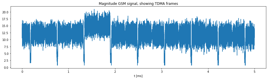
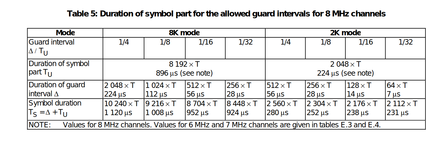
GSM uses time division to share a frequency channel among users. Each frequency is divided into blocks of time that are known as time-slots. 8 time-slots are numbers TS0 – TS7. Each time slot lasts about 576.9 μs. The bit rate is 270.833 kb/s, a total of 156.25 bits can be transmitted in each slot.
Each slot allocates 8.25 of its „bits time“ as guard-time, split between the beginning and the end of each time slot. Data transmitted within each time slot is called a burst. There are several types of bursts.
Frequency correction burst is a burst of a pure frequency tone at 1/4th the bitrate of GSM or (1625000 / 6) / 4 = 67708.3 Hz. By searching a channel for this pure tone, we can determine its clock offset by determining how far away from 67708.3Hz the received frequency is.
How is it working?
- Scanning of GSM Channels is based on the ARFCN frequency bands. For tuning into GSM Frequency, the ARFCN script can be used. We give the input of band to scan, the result will be the frequency. If we input the „scan all“ option, it will scan the whole GSM Frequencies in the given band and return the offset calculated from each frequencies. The code for the same can be found at: https://github.com/aerospaceresearch/CalibrateSDR/blob/jyrj_dev/calibratesdr/gsm/arfcn_freq.py
- After scanning channels in specific bands using ARFCN, the program will record the sample in the given sample rate. Make sure the SDR is connected with the device, or we can record it and give the input as a wave file.
- The determination of the position of FCCH bursts that we receive in SDRs is done by the code in fcch_ossfet.py. We measure it by how much shifted is the FCCH burst, than what we expect, that is at 67708.3 Hz from the frequency centre. Simply, if no offset is there, we could see these tone bursts at 67708.3 Hz offset concerning the centre frequency of the channel.
- The final output we receive include
- Frequency drift from the expected FCCH position
- The Offset of SDR in PPM
- The whole code works from the main cali.py and inturns gsm.py files
To test with the IQ_file.wave:
After cloning the repo locally, run the setup to install the requirements using the command: python setup.py install
After that, to run the visualization plots, run:
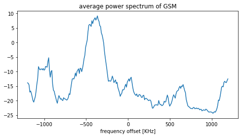
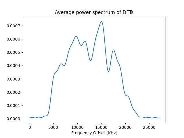
python cali.py -m gsm -f <location of wav file> -rs <sampling rate> -fc <frequency center>First, we will get the plot of the average power spectrum plot. Play with the code to increase the N value, and you can see the sharpness of the line.
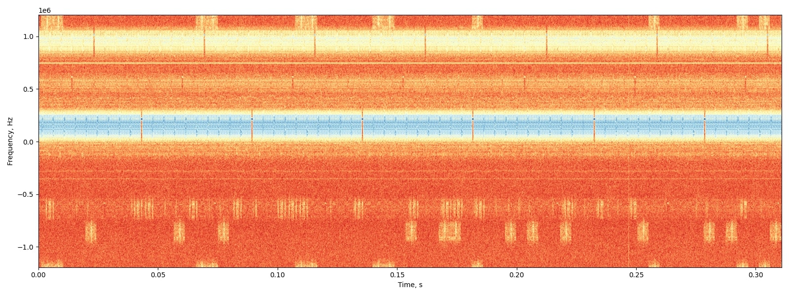
Further plots generated includes TDMA frames, the position of FCCH bursts visualisation as given below.

We can see the pure tone FCCH bursts are occurring at specific intervals and can be visualized as small blue dots at a range of 0.25 from the centre.
Thus implementation of a filter bank and calculating the positions of these FCCH bursts will give us the offset frequency since we know these FCCH bursts occur at a distance of 67708.3 Hz from the frequency centre.
Usage
Test files for GSM, recorded by Andreas can be found here.
- Setup the environment, make sure the requirements are installed (preferably in a virtualenv). Use the setup.py to install necessary requirements.
- To view the parameters for input run
~$ python cali.py -h
usage: cali.py [-h] [-f F] [-m {dab,dvbt,gsm}] [-s {rtlsdr}] [-c C] [-rs RS] [-rg RG] [-rd RD] [-nsec NSEC] [-gr] [-v] [-fc FC]
optional arguments:-h, –help show this help message and exit-f F select path to input file-m {dab,dvbt,gsm} select mode-s {rtlsdr} scan with rtlsdr-c C scan by „all“ channels, by channel number „0,1,…n“ or by block name-rs RS file/scan sample rate-rg RG scan with gain-rd RD scan with the device-nsec NSEC scan for n-seconds-gr, –graph activate graphs-v, –verbose an optional argument-fc FC frequency centreSetup the environment, make sure the requirements are installed (preferably in a virtualenv). Use the setup.py to install necessary requirements.
- If testing with a recorded wav file, enter the parameters as:
~$ python cali.py -m gsm -f <location of wav file> -rs <sampling rate> -fc <frequency center>- If testing with an SDR stick, specify the ARFCN band, or specific frequency centre to scan for the GSM channel.
The ARFCN Bands include: GSM_850, GSM_R_900, GSM_900, GSM_E_900, DCS_1800, PCS_1900. For more information about the arfcn, checkout here.
Example usage:
~$ python cali.py -m gsm -s rtlsdr -c 900The above parameters can be changed according to user needs. -rs can be specified with sample rate. The exact sample rate will be shown with the result. Make sure the SDR is connected when running the code with -s rtlsdr argument. Specify the -fc frequency argument, if the scan is to be done with a single frequency.
The expected output would look like this:
{'f': None, 'm': 'gsm', 's': 'rtlsdr', 'c': '900', 'rs': 2048000, 'rg': 20, 'rd': 0, 'nsec': 10, 'graph': False, 'verbose': False, 'fc': None}
let's find your SDR's oscillator precision
scanning…
starting mode: gsm
Found Rafael Micro R820T/2 tuner
Exact sample rate is: 270833.002142 Hz
Scanning all GSM frequencies in band: GSM_900
Offset Frequency: 31031.66666666667
Offset in PPM: 33.179448397684716
The Offset calculated from the frequency drift between fcch positions can be precisely derived and can be used to correct the oscillator.
Potential further improvements:
- LTE Signal support need to be included (currently in focus), and much more standards need to be made compatible for a wide usage of the tool.
- Making a platform-neutral API to communicate with more SDR devices.
- Optimising the user interface (command-line tool can be made more user friendly).
References:
Find out the project updates in my branch and do give a star for the project in AerospaceResearch org:
https://github.com/aerospaceresearch/CalibrateSDR/tree/jyrj_dev
- https://jyrj.hashnode.dev/how-i-got-selected-for-gsoc – First blog
- https://aerospaceresearch.net/?p=2208 – Second blog
- https://aerospaceresearch.zulipchat.com/#narrow/stream/281823-CalibrateSDR – Chat stream for the project
- https://greenteapress.com/wp/think-dsp/ – For anyone who likes to start with digital signal processing
- https://pysdr.org/index.html – A simple guide to learning the basics of SDRs and DSP

![[GSoC2021] CalibrateSDR GSM Support – first coding period](https://aerospaceresearch.net/wp-content/uploads/2021/06/CalibrateSDR-1.png)