In the previous blog:
I discussed about how I am decoding the position of the aircraft from 2 ADS-B frames and also from 1 ADS-B frame and a reference position and how I found both handsome and erractic readings.
Let’s look into how other airborne parameters, such as ‚aircraft identity‘ and ‚velocity‘ are being decoded and calculated.
There is a special type of frame which is known as ‚Enhanced Mode-S‘ frames. They also contain similar information at times like the non-Enhanced Mode-S frames. I will elaborate on both in this blog.
Frames with downlink format 20 & 21 are known as Enhanced Mode-S frames.
The following methods were implemented in the code for decoding the information from the ADS-B frames.
Aircraft Identification
Frames with Downlink Format 17-18 and Type Code 1-4 are known as aircraft identification messages.
The structure of the 56-bit DATA field of any such aircraft identification frame will be as follows:
| TC | EC | C1 | C2 | C3 | C4 | C5 | C6 | C7 | C8 |
| 5 | 3 | 6 | 6 | 6 | 6 | 6 | 6 | 6 | 6 |
TC: Type Code
EC: Emitter Code
Second row signifies the bit-length
The EC value with regard to the TC value determines the type of aircraft (Such as : Super, Heavy, light etc). When the EC is set to ‚zero‘ signifies such information is not being transmitted by the aircraft.
An Airbus A380 is known as 'Super' and a Boeing 777-300ER is known as 'Heavy'. Small, private or training aircrafts such as Cessna 172s are known as 'Light'.
For determining the callsign a lookup table is used:
#ABCDEFGHIJKLMNOPQRSTUVWXYZ#####_###############0123456789######‚#‘ signifies a null value and ‚_‘ signifies a space between two words.
Let us take an Aircraft identifier frame recorded by one of our ground stations:
a0001910200490f1df2820700716
Thus the DATA part of this frame is:
200490f1df2820
| BIN | 00100000 | 000001 | 001001 | 000011 | 110001 | 110111 | 110010 | 100000 | 100000 |
| INT | 4 | 1 | 9 | 3 | 49 | 55 | 50 | 32 | 32 |
| CHAR | [TYPE CODE] | A | I | C | 1 | 7 | 2 | _ | _ |
The integer number corresponds to the corresponding element in the lookup table array.
Thus, the decoded callsign is „AIC172“ which belongs to Air India on the route 172
BDS 2,0 frames are also known as Aircraft Identification Messages. In these frames the first 8 bit of the DATA segment contains the BDS number and the rest is same as the previous one.
Airborne Velocity
ADS-B frames with Downlink Format 17-18 and TC 19 contain the velocity information of the aircraft.
Subtype 1 (Ground Speed)
The typical structure of the frame:
| Position in frame | Position in data block | Length | Abbreviation | Data |
|---|---|---|---|---|
| 33 – 37 | 1 – 5 | 5 | TC | Type code |
| 38 – 40 | 6 – 8 | 3 | ST | Subtype |
| 41 | 9 | 1 | IC | Intent flag |
| 42 | 10 | 1 | RESV_A | Reserved-A |
| 43 – 45 | 11 – 13 | 3 | NAC | Velocity uncertainty (NAC) |
| 46 | 14 | 1 | S_ew | East-West velocity sign |
| 47 – 56 | 15 – 24 change | 10 | V_ew | East-West velocity |
| 57 | 25 | 1 | S_ns | North-South velocity sign |
| 58 – 67 | 26 – 35 | 10 | V_ns | North-South velocity |
| 68 | 36 | 1 | VrSrc | Vertical rate source |
| 69 | 37 | 1 | S_vr | Vertical rate sign |
| 70 – 78 | 38 – 46 | 9 | Vr | Vertical rate |
| 79 – 80 | 47 – 48 | 2 | RESV_B | Reserved-B |
| 81 | 49 | 1 | S_Dif | Diff from baro alt, sign |
| 82 – 88 | 50 – 56 | 7 | Dif | Diff from baro alt |
These two bits determine the direction at which the aircraft was flying:
S_ns:
     1 -> flying North to South
     0 -> flying South to North
 S_ew:
     1 -> flying East to West
     0 -> flying West to East
The speed and the heading can thus be computed by:
If the calculated heading is negative, then we add 360 to it.
Vertical Speed
The S_Vr bit (69) determines the direction(ascent/descent).
0- Up
1- Down
Therefore the actual speed is calculated by:
V = (int(Vr) – 1) * 64
Therefore, V is the speed and S_Vr states whether the aircraft is climbing or descending.
The VrSrc field (Vertical Rate Source) determines the measured altitude type:
0 - Barometric altitude rate
1 - Geometric altitude rate
Subtype 3 (AirSpeed)
Here let us see how the structure of Subtype 3 differs from Subtype1:
| Position in frame | Position in data block | Length | Abbreviation | Data |
|---|---|---|---|---|
| 33 – 37 | 1 – 5 | 5 | TC | Type code |
| 38 – 40 | 6 – 8 | 3 | ST | Subtype |
| 41 | 9 | 1 | IC | Intent change flag |
| 42 | 10 | 1 | RESV_A | Reserved-A |
| 43 – 45 | 11 – 13 | 3 | NAC | Velocity uncertainty (NAC) |
| 46 | 14 | 1 | S_hdg | Heading status |
| 47 – 56 | 15 – 24 | 10 | Hdg | Heading (proportion) |
| 57 | 25 | 1 | AS-t | Airspeed Type |
| 58 – 67 | 26 – 35 | 10 | AS | Airspeed |
| 68 | 36 | 1 | VrSrc | Vertical rate source |
| 69 | 37 | 1 | S_vr | Vertical rate sign |
| 70 – 78 | 38 – 46 | 9 | Vr | Vertical rate |
| 79 – 80 | 47 – 48 | 2 | RESV_B | Reserved-B |
| 81 | 49 | 1 | S_Dif | Difference from baro alt, sign |
| 82 – 88 | 50 – 66 | 7 | Dif | Difference from baro alt |
Heading
The S_hdg bit shows whether heading data is available or not:
0 - Heading data not available
1 - Heading data available
If heading data is available then it is calculated by:
Heading = Hdg(10 bit data) * 360/1024
Velocity (Airspeed)
Simply converting the AS bits gives the airspeed in knots.
Vertical Rate is calculated in the same manner as in Subtype 1
Enhanced Mode-S:
Aircraft Intention (BDS4,0)
The structure:
| Field | Position | Length |
| Status | 1 | 1 |
| MCP selected altitude Precision = 16ft | 2-13 | 12 |
| Status | 14 | 1 |
| FMS selected altitude Precision = 16ft | 15-26 | 12 |
| Status | 27 | 1 |
| Barometric setting (in mb and not hPa) Value is actual minus 800 Precision = 0.1mb | 28-39 | 12 |
| Reserved | 40-47 | 8 |
| Status | 48 | 1 |
| VNAV hold state | 49 | 1 |
| ALT hold state | 50 | 1 |
| APP hold state | 51 | 1 |
| Reserved | 52-53 | 2 |
| Status | 54 | 1 |
| Altitude source: 00: Unknown 01:Aircraft altitude 10: MCP set altitude 11: FMS set altitude9 | 55-56 | 2 |
Note: MCP stands for Mode Control Panel where the pilot feeds in the data to the autopilot
FMS stands for Flight Management Computer where the data is fed to calculate various other flight parameters.
Track and Turn (BDS 5,0):
Many more information is given such as roll angle, true track angle etc:
| Field | Position | Length |
| Status | 1 | 1 |
| Sign, 1 | 1 | 1 |
| Roll angle range = [-90, 90] degrees Precision = 45/256 degree | 3-11 | 9 |
| Status | 12 | 1 |
| Sign | 13 | 1 |
| True Track angle Precision: 90/512 degree- | 14-23 | 10 |
| Status | 24 | 1 |
| Ground Speed Precision: 2 knots | 25-34 | 10 |
| Status | 24 | 1 |
| Sign | 36 | 1 |
| Track angle rate Precision: 8/256 degree/second | 37-45 | 8 |
| Status | 46 | 1 |
| True Airspeed Precision: 2 knots | 47-56 | 10 |
Note: The sign bit determines whether to use 2's complement to determine the value present after it. It it is set to '1' then we have to use 2's complement.
Airspeed and Heading (BDS 6,0)
A lot more information is conveyed in this kind of frames:
| Field | Position | Length |
| Status | 1 | 1 |
| Sign | 1 | 1 |
| Magnetic Heading Precision = 90/512 degree | 3-12 | 10 |
| Status | 13 | 1 |
| Indicated Airspeed Precision: 1 knots | 14-23 | 10 |
| Status | 24 | 1 |
| Mach (speed) Precision: 2.048/512 Mach | 25-34 | 10 |
| Status | 35 | 1 |
| Sign | 36 | 1 |
| Barometric altitude rate Precision: 32 feet/ minute | 37-45 | 9 |
| Status | 46 | 1 |
| Sign | 47 | 1 |
| Inertial altitude rate Precision: 32 ft/minute | 48-56 | 9 |
Unfortunately the percentage of decodable Enhanced Mode-S message received was very low in both short recordings and long recordings which was worth hours.
File overlap checker:
The ground stations were programed to span each recorded file for 2 minutes(approx.). Now this means that for a long duration, there will be an array of files from several ground stations.
There has to be a logic, where the code finds all the files from several ground stations recorded at the same or has overlapping recording times and club them together for the next step.
I identified few such cases of overlaps:
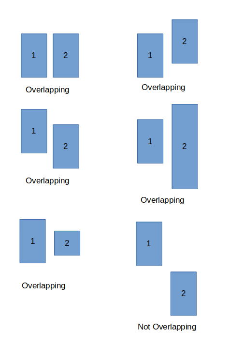
The overlapping files are clubbed together into a list for further processing.
Next step is to find the same frames present in different station recordings, so we need to know the files that overlap and process it accordingly.
Feel free to get in touch with me:
- https://twitter.com/shoumik_dey
- https://github.com/shoumikdey
- shoumik.dey@aerospaceresearch.net