This blog post will cover the process of visualization of NOAA images, specifically we will talk about general visualization pipeline and different ways to visualize satellite imagery, including creating interactive web maps and virtual globes.
Visualization pipeline
We shall start from the very beginning. NOAA satellites constantly scan the Earth’s surface and then transmit it as a radio wave signal. This signal is captured by SDR (Software-defined radio system) and saved in wav format. Next step is dedicated to decoding this signal, i. e. finding sync signals, extracting and decoding an image line-by-line.
The decoded image includes both sync signals and 2 variants of the scanned image (in different color schemes), therefore it requires one more preprocessing step, where it is being cropped and rotated. Next two images are the results of this step, they will be used as an example for visualization.
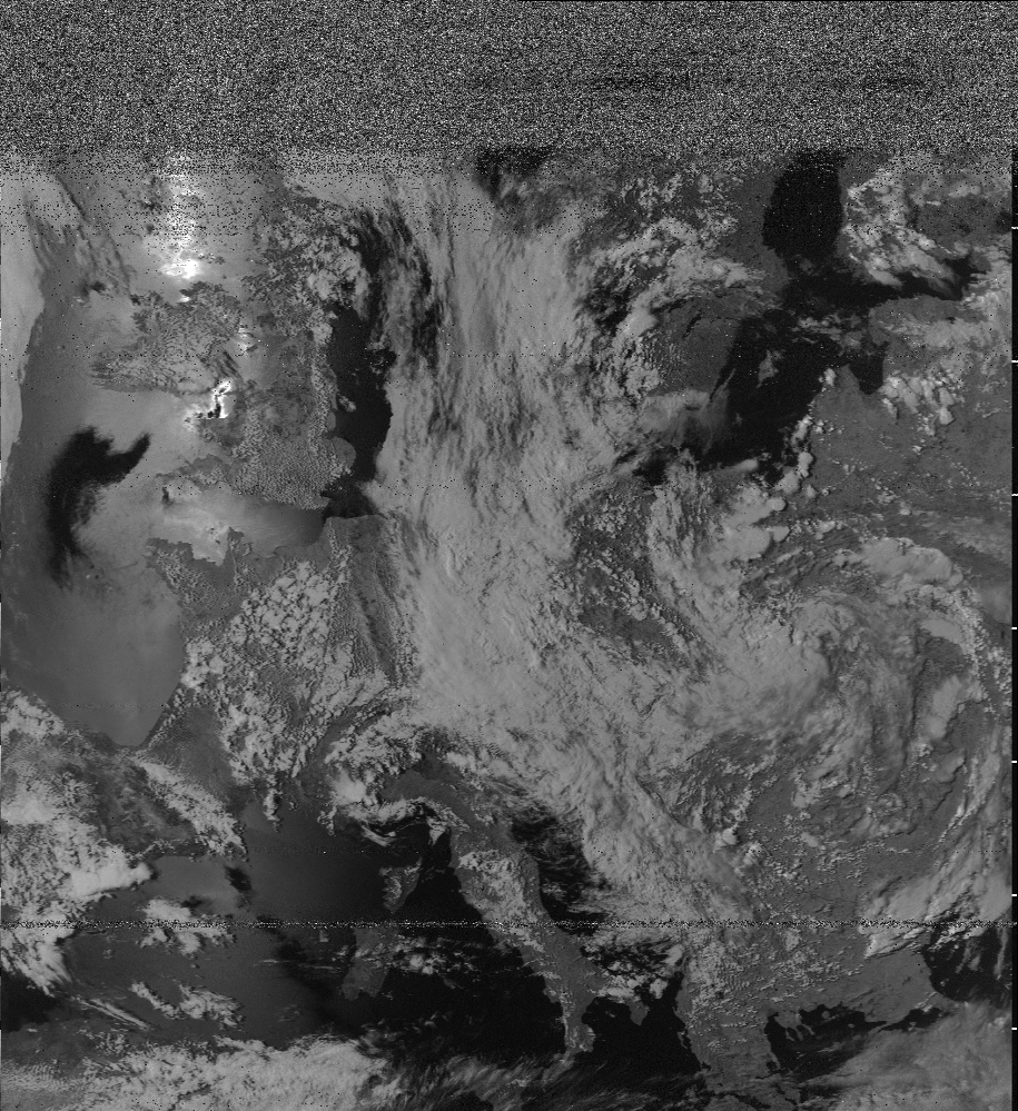
Figure 1. Example of decoded image.
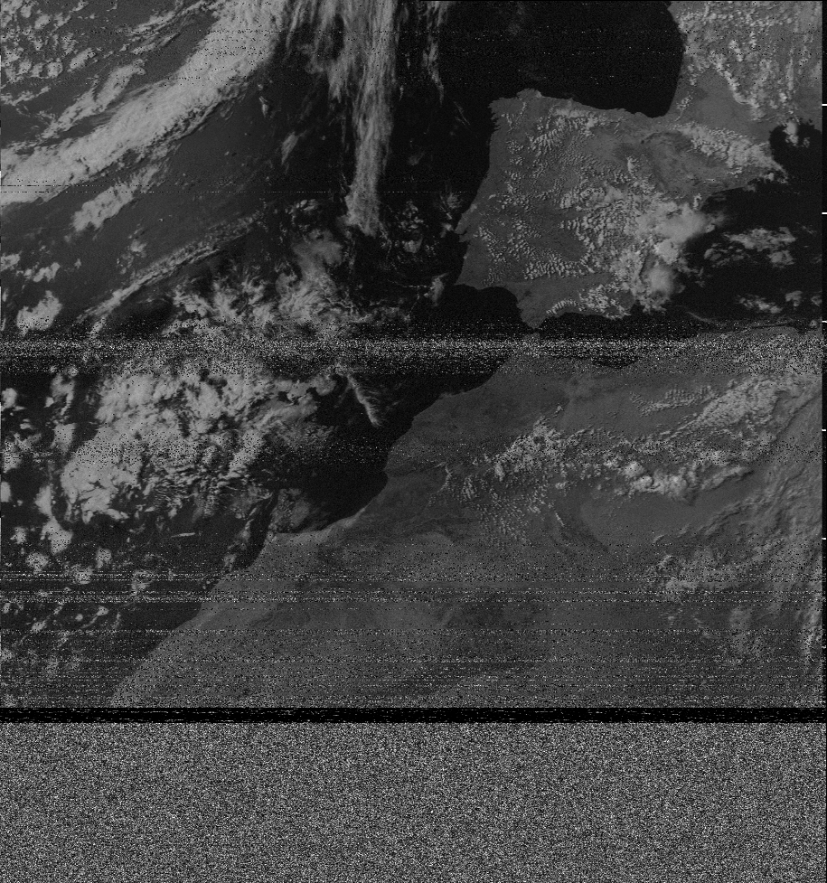
Figure 2. Example of decoded image.
Next step is georeferencing, which has already been described in previous post [1]. On this step, the coordinate system will be assigned to the image, every pixel will have a corresponding geographic coordinates. Main computation is done with gdal library.
Merging images
The goal of the project is to primarily create tools, that could visualize a set of satellite images. It means that we must find a way to combine several images into one standalone raster, which we could then display as a web map or as a virtual globe.
Using tools from image analysis (image stitching) would be a bad approach, because of two reasons:
- these methods are approximate in their’s nature
- do not take in account image distortions
A better approach would be to use pixel’s coordinates. We know the coordinates of each pixel, thus we could tell exactly where it will be located on the new image. For overlapping areas, for each pixel we will have one of 3 cases:
- no pixels mapped to this pixel
- 1 pixel is mapped is mapped to this pixel
- several pixels mapped to this pixel
If no pixels have been map to the position, then it will be filled with special no-data value. If there is one pixel, then it’s value will be assigned to the corresponding pixel on new image. If there are several candidates for certain pixel, we will compute new pixel value from them based on some strategy, for example taking max or average. In this example we’ll use averaging for overlapping regions. Below is an example of merging 2 images above, country boundaries added for clarity.
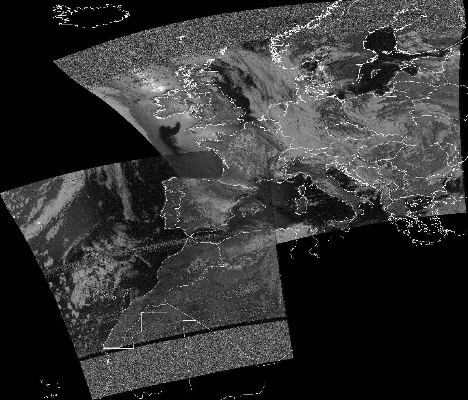
Figure 3. Example of merged satellite images.
As you may see, there is still a contrast present between the images and the overlapping part, the reason for this are different lightning conditions for images. Nevertheless, image quality with this method outperforms other methods, like taking maximum for example.
Creating TMS
On this step our raster will be transformed to yet another representation, which will be used for further visualization.
TMS (Tile Map Service) – is a protocol for serving maps as tiles i. e. splitting the map up into a pyramid of images at multiple zoom levels [2]. See the image to better understand the concept.
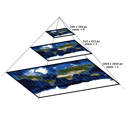
Figure 4. Tiles pyramid.
So for each level zoom level a set of tiles is generated, each tile has it’s own resolution and will be displayed at specific position at specific zoom. To generate this set of tiles gdal2tiles.py program is used, it transforms an input raster into a directory tree with tiles [3].
It should be noted that TMS is not the only choice here, another alternative is WMS (Web Map Service) [4].
Interactive web-maps
Finally, having TMS tiles computed we could create a web map. To do this we will use leaflet.js, which is a library for web-mapping applications. [5] We will combine two layers, the first one is our tiled raster, which will be loaded from local directories and the second one is Open Street Map layer which will be loaded from OSM site. The code for map is contained in the map.html file and could be opened directly in browser. You can see a live example here https://caballeto.github.io/map.html, or in the iframe below.
Virtual globe
Another way to visualize satellite images is of course to plot them on virtual globe. Once again we could use already computed TMS tiles here. To render the globe we will use webglearth2 library, which is created exactly for this purpose. Similarly to a web map, we will add an OSM layer as a background layer. To open it locally you will have to start an http server, and then open the globe.html via http. Running commands (run from directory where globe.html is stored):
python -m http.server 8000- go to browser and connect to
localhost:8000/globe.html.
Or you can simply take a look at an online version below, better view at https://caballeto.github.io/globe.html.
Software
To create presented visualizations for a raster, you can use generate_map.py tool from directdemod package. It will automatically create tiles from your raster and then will generate corresponding map.html and globe.html files.
Conclusion
In this post we’ve looked at different ways and tools for raster visualization, specifically we’ve analysed the visualization pipeline for satellite imagery. Presented types of visualizations are compatible with many different mapping applications (leaflet, openlayers etc.) and could be easily published and used on the Internet.